
High-Accuracy Ball Screws: Which Lead, Preload, and Accuracy Grade Fit Your Axis?
A ball screw is often treated as a catalog line item: choose a diameter, pick a lead, select an accuracy grade, and move on. That approach can work for a lightly loaded utility axis, but it becomes risky when the machine must hold micron-level positioning, reverse direction frequently, or maintain stable output through long production cycles.
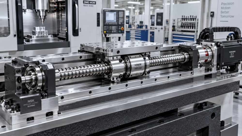
For technical evaluators, selecting high accuracy ball screws is a system decision rather than a component decision. Lead influences motor speed, force multiplication, and resolution. Preload determines lost motion, rigidity, heat generation, and available life. Accuracy grade affects positioning error over travel, but it cannot correct a weak support arrangement, a thermally unstable layout, or poor servo tuning.
The practical question is not “Which specification is best?” It is: Which combination produces acceptable motion at the required speed, load, temperature, and maintenance interval? This guide provides a disciplined way to make that choice for CNC machine axes, grinding equipment, robotics, inspection systems, automation modules, and other precision motion applications.
Start with the axis—not the ball screw catalog
Before comparing grades or preload classes, define what the axis is truly expected to do. A vertical Z-axis lifting a spindle head has a different risk profile from a short-stroke pick-and-place slide. A 1.5 m milling axis operates differently from a compact semiconductor fixture, even when both claim similar positioning requirements.
A useful evaluation sheet should capture the following conditions:
- Required travel, usable stroke, and overall screw length
- Maximum and typical feed rate
- Acceleration, deceleration, dwell time, and duty cycle
- External cutting force, process force, or handling load
- Horizontal, vertical, or inclined mounting orientation
- Positioning accuracy, repeatability, and reversal requirements
- Ambient temperature, local heat sources, and lubrication method
- Expected life, maintenance access, contamination exposure, and safety consequences of failure
This initial work prevents a common purchasing mistake: specifying an ultra-precise screw for an axis whose dominant error comes from bearings, structure, encoder feedback, or thermal growth. Conversely, a low-cost rolled screw may appear acceptable on paper while backlash and lead error become visible in finished parts, contouring quality, or automated assembly yield.
Lead selection: the speed-versus-force decision that shapes the whole drive
The lead is the linear distance the nut travels during one screw revolution. A 5 mm lead moves the axis 5 mm per revolution; a 20 mm lead moves it 20 mm. It sounds simple, yet lead affects nearly every part of the motion chain.
A smaller lead increases mechanical advantage. For the same axial load, it generally requires less motor torque, making it attractive for high-force axes, compact servo motors, vertical loads, and applications where holding force matters. It also gives finer theoretical linear resolution for a given encoder count.
But smaller lead demands higher rotational speed to achieve the same linear velocity. At long travel lengths, that can bring the screw closer to its critical speed limit, increase rotational losses, and make high-speed machining or rapid traverse impractical.
A larger lead provides more linear travel per revolution. This supports faster rapid movement at lower screw rpm, which is useful for long CNC axes, gantry automation, material handling, and high-throughput machines. The trade-off is reduced mechanical advantage: the servo motor and gearbox, if used, must deliver more torque to move the same load.
For a first check, screw speed can be estimated as:
Screw speed (rpm) = linear speed (mm/min) ÷ lead (mm/rev)
If an axis must reach 30,000 mm/min, a 10 mm lead requires 3,000 rpm, while a 20 mm lead requires 1,500 rpm. That difference can materially affect critical-speed margin, motor selection, bearing preload, and thermal behavior.
Do not choose a large lead solely because it makes rapid travel look impressive. A coarse lead can reduce effective stiffness at the tool point if the entire system is not sized accordingly. It may also expose problems in braking, vertical-axis holding, and force control. In precision grinding, fine boring, metrology, or low-speed contouring, the smoothness and force sensitivity associated with a moderate or fine lead can be more valuable than maximum traverse speed.
A practical lead-selection lens
In real evaluations, lead should be reviewed with screw diameter and unsupported length. A fast lead paired with a slender, long screw may be the wrong combination even when motor calculations look comfortable. The limiting issue is often shaft dynamics rather than nominal torque.
Preload: eliminating lost motion without creating a heat problem
Preload applies internal axial force between the balls, nut raceways, and screw groove geometry. Its primary purpose is to reduce axial clearance and improve rigidity. In a reversing axis, this matters immediately: without adequate preload, the command may change direction before the table, carriage, or tool begins to move.
For high accuracy ball screws, preload is not simply an “on” or “off” feature. It is a controlled compromise. Higher preload usually improves axial stiffness and reduces backlash, helping the axis resist changing cutting forces. Yet it also raises friction torque, heat generation, and contact stress. Excessive preload can shorten service life and cause positioning drift as the nut temperature rises.
Low or light preload is often appropriate when the axis is lightly loaded, runs at elevated speed, or relies on compensation and closed-loop feedback for moderate positioning needs. It reduces running torque and supports lower operating temperature. The limitation appears during direction changes or varying process forces, where compliance may show up as contour error or settling delay.
Medium preload is frequently the balanced choice for general CNC machining centers, precision automation, and many industrial handling systems. It provides meaningful rigidity without imposing the thermal penalty associated with very aggressive preload.
High preload has a place in short-stroke, high-rigidity applications such as grinding slides, precision measuring equipment, certain mold machining operations, and axes exposed to rapidly changing process loads. It should be specified only after considering lubrication, duty cycle, thermal paths, and support-bearing stiffness. A highly preloaded nut on a continuously cycling axis can create a machine that is accurate after warm-up only if thermal compensation is carefully managed.
Questions that reveal the right preload range
Ask what happens at reversal. If the axis changes direction under significant cutting load, nut rigidity and backlash control deserve priority. Ask what happens during a long shift. If the machine cycles continuously at high feed rates, friction heat may matter more than static rigidity. Ask whether the process measures absolute position, repeatability, or finished-part geometry. These are related, but they are not identical requirements.
Also distinguish between screw backlash and total axis lost motion. Couplings, angular-contact support bearings, gearbox compliance, mounting interfaces, and carriage structure can all contribute. Increasing ball nut preload cannot compensate for a weak bearing block or an inadequately rigid machine frame.
Accuracy grade: understand what the grade actually controls
Ball screw accuracy grades normally describe lead accuracy and variation over defined travel lengths, using the applicable manufacturer standard or regional standard system. A higher grade generally means tighter control of cumulative lead error and lead variation. This supports more predictable axis positioning, especially across long travel.
However, accuracy grade should not be confused with final machine accuracy. A precision-ground screw with a tight lead specification can still produce poor part geometry if installation alignment is incorrect, the nut mount distorts under load, bearings settle, or temperature changes substantially from assembly conditions.
For selection purposes, it helps to separate three performance targets:
- Positioning accuracy: how closely the axis reaches the commanded location across its travel.
- Repeatability: how consistently it returns to the same point under the same approach and operating condition.
- Bidirectional accuracy: how closely positions match when approached from opposite directions, influenced heavily by backlash and structural compliance.
A high-grade ground ball screw is generally justified when uncompensated positioning error must be low, when the machine performs precision interpolation, or when stable geometric accuracy is a commercial requirement. Typical examples include high-end machining centers, grinding machines, coordinate inspection systems, precision assembly equipment, and advanced optical or medical manufacturing platforms.
For many production machines, a less stringent grade combined with laser calibration and CNC pitch-error compensation can be a rational engineering choice. Compensation can correct predictable lead error, but it cannot fully solve friction variation, local damage, thermal expansion, backlash changes, or installation-induced distortion. It is most effective when the mechanical system is already stable.
Ground versus rolled screws: avoid an oversimplified comparison
Rolled ball screws are commonly selected for cost-sensitive automation, general handling, packaging, and moderate-accuracy equipment. They can offer dependable operation when the load, speed, alignment, and contamination conditions are properly controlled. A rolled screw is not automatically unsuitable simply because an application uses servo control.
Ground ball screws are typically chosen where tighter lead accuracy, smoother running characteristics, controlled preload options, and higher motion precision are required. Their value becomes clearer in applications where process quality depends on the axis itself: precision milling, grinding, EDM, high-resolution inspection, complex contouring, and tooling systems.
The decision should reflect the cost of axis error. If a small positioning deviation creates scrap, requires repeated inspection, causes assembly mismatch, or threatens an expensive workpiece, the case for a precision-ground solution becomes stronger. If the process tolerance is relatively open and throughput is the main driver, a well-designed rolled screw arrangement may deliver better overall value.
Long axes introduce two concerns that catalogs cannot hide: dynamics and temperature
As screw length increases, critical speed and buckling become central design checks. Critical speed concerns rotational whirling; buckling concerns compressive axial loading. Support configuration—fixed-fixed, fixed-supported, or fixed-free—changes the allowable limits substantially. The wrong end-support arrangement can turn a theoretically suitable screw into a vibration source at operating speed.
Long screws also expand with temperature. Even a small temperature rise over a long axis can create meaningful positional shift. Heat can come from the nut, support bearings, motor, cutting environment, or nearby hydraulic and pneumatic equipment. A preloaded nut raises the importance of this issue.
Possible responses include a fixed-floating support layout, thermal growth compensation in the control system, temperature monitoring, controlled lubrication, shaft cooling where appropriate, and machine layouts that isolate heat sources. The right answer depends on whether the machine needs absolute accuracy immediately after startup or can operate through a managed warm-up cycle.
Selection mistakes that deserve a formal review
Choosing accuracy grade before defining compensation strategy. Determine whether the machine uses direct feedback, pitch compensation, thermal compensation, or none of these. The screw grade should support the complete control architecture.
Using preload as a cure for every error. More preload may improve reversal behavior, but it increases torque and temperature. Review total stiffness from motor coupling through carriage structure.
Ignoring lubrication and contamination. Fine particles, coolant ingress, poor wiper design, and inconsistent lubricant delivery can degrade a precision ball screw faster than a modest difference in catalog grade. Bellows, covers, seals, correct lubricant type, and maintenance access are part of the motion specification.
Evaluating only peak load. Life calculations should reflect the real duty cycle, including frequent light-load movement, intermittent process force, acceleration events, and vertical holding conditions. Peak load alone rarely describes fatigue exposure accurately.
Assuming nominal catalog dimensions guarantee interchangeability. Nut mounting interfaces, end machining, bearing-seat tolerances, preload condition, lubrication ports, and delivery condition all need confirmation before procurement.
A decision path for technical evaluators
Begin by setting the allowable positioning, repeatability, and reversal error at the work point—not merely at the motor encoder. Then establish required velocity and acceleration. Use these to narrow the lead range. Check motor torque, rpm, reflected inertia, critical speed, and buckling with the actual support configuration.
Next, select preload according to reversal load, required rigidity, duty cycle, and thermal tolerance. Choose the accuracy grade based on uncompensated error needs and the machine’s calibration strategy. Finally, verify life, lubrication, sealing, mounting alignment, inspection documentation, and replacement requirements.
The best high accuracy ball screw is rarely the one with the highest grade, the strongest preload, or the fastest lead in isolation. It is the one whose lead, preload, accuracy, diameter, support design, and maintenance plan work together without creating hidden thermal or dynamic problems. For engineering teams evaluating suppliers or developing a new axis, that systems view turns a component choice into a reliable motion platform.
Related News
- How PU Hydraulic Seal Kits Reduce Leakage in High-Cycle Cylinder RepairsSep 25, 2026Fluid Power Control Strategist
- Selecting Needle Roller Thrust Bearings for High Axial Loads and Limited SpaceSep 25, 2026Tribology & Kinematics Expert
- Why Heat-Treated Forged Rollers Develop Surface Cracks and Fail PrematurelySep 25, 2026Foundry Phase-Change Fellow
- What to Audit at a Tool Steel Factory Before Approving a Production SupplierSep 25, 2026CNC Kinematics Architect
- High-Accuracy Ball Screws: Which Lead, Preload, and Accuracy Grade Fit Your Axis?Sep 25, 2026
- Why Gear Motors Overheat: Load, Duty Cycle, and Ventilation ChecksSep 24, 2026Tribology & Kinematics Expert