
Expansion Joints in Piping: Preventing Fatigue from Thermal Movement
Expansion Joints in Piping: Preventing Fatigue from Thermal Movement
A piping system rarely fails because one component was obviously undersized on paper. More often, failure develops quietly: a pump nozzle begins to see unexpected load, a valve becomes difficult to operate, a flange gasket starts weeping after repeated temperature cycles, or a welded branch connection develops a fatigue crack. Thermal movement is frequently behind these problems.
As pipes heat up, they expand. As they cool, they contract. In a long straight run, that movement can become significant even when the temperature change appears modest. If the line is restrained without a deliberate movement-management strategy, the pipe will transfer stress into supports, anchors, equipment connections, fittings, and welds. Expansion joints are one way to introduce controlled flexibility, but they are not a universal cure. Their value depends on correct selection, proper restraint design, and installation discipline.
For project managers, the practical question is not simply whether to specify expansion joints in piping. It is where movement will occur, what the system can safely absorb, and whether the selected joint will work with the actual supports, pressure conditions, maintenance access, and connected equipment.
Thermal movement becomes a fatigue problem when it has nowhere to go
Most piping materials change length as temperature changes. The amount depends on the pipe material, installed length, operating temperature range, and the temperature at which the system was assembled. A short connection near a heat exchanger may tolerate that movement through local flexibility. A long steel header between rigidly supported structures may not. Plastic-lined lines, stainless steel piping, ductile iron systems, and composite assemblies can each require different consideration because their thermal behavior, joint arrangements, and allowable loads are not the same.
The risk is especially high in systems that cycle rather than operate at one steady condition. Steam services, hot-water loops, thermal oil piping, exhaust ducting, process lines with batch heating, and outdoor pipelines exposed to seasonal variation all experience repeated expansion and contraction. One thermal event may not cause visible damage. Hundreds or thousands of cycles can gradually fatigue a weld toe, bellows convolution, bracket, anchor point, or equipment nozzle.
A common project mistake is treating thermal growth as a piping-only issue. In reality, it crosses disciplines. Civil teams may provide a rigid pipe rack connection where a sliding support was expected. Mechanical teams may connect a line to a pump or compressor without confirming nozzle load limits. Procurement may substitute a joint with a similar face-to-face dimension but different movement capability or pressure thrust behavior. By commissioning, the system can look complete while carrying stress it was never designed to carry.
What expansion joints actually do—and what they do not do
Expansion joints provide a controlled path for movement. Depending on their construction, they may accommodate axial compression and extension, lateral offset, angular rotation, or a combination of these movements. Metallic bellows expansion joints are common in higher-temperature and pressure-sensitive services. Rubber expansion joints are often used where vibration isolation, noise reduction, moderate movement, or flange misalignment are also concerns. Fabric expansion joints are more typical in low-pressure gas, air, flue gas, and duct applications.
The important word is controlled. A joint should be selected for a defined movement case, not installed as a flexible-looking insurance policy. It does not eliminate the need for anchors and guides. It does not automatically protect equipment from poor alignment. It does not compensate for unsupported pipe weight, pressure thrust, water hammer, excessive vibration, or a line that was forced into position during installation.
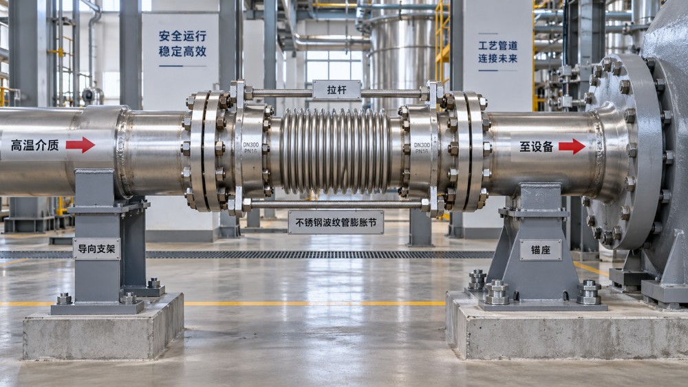
A bellows unit in particular deserves careful treatment. Internal pressure creates an axial force that tries to extend the assembly. Unless the expansion joint is designed with restraints such as tie rods, hinges, gimbals, or a pressure-balanced arrangement, that force must be carried by the piping system’s main anchors. If those anchors are absent, undersized, or located incorrectly, the joint can overextend or the pipe can shift in an unexpected direction.
Start with the movement case, not the catalog page
The most reliable selection process begins with the piping layout. Identify fixed points, likely thermal growth directions, elevation changes, branches, valves, and equipment connections. Then establish the installed condition and the full operating envelope, including start-up, shutdown, upset conditions where relevant, and ambient exposure. A line that is installed during hot weather but operates much colder may need to accommodate contraction as well as expansion.
Movement should be separated into axial, lateral, and angular components. This sounds basic, but it prevents an expensive mismatch. An axial expansion joint is usually efficient for straight-line growth when correctly anchored and guided. It is not automatically suitable for large lateral displacement. A universal expansion joint, generally consisting of two bellows connected by a center spool, can accommodate lateral movement more effectively, but its footprint and support needs must be planned. Hinged and gimbal assemblies manage angular movement while restraining pressure thrust in specific directions. The geometry of the system determines which approach makes sense.
There are also cases where an expansion loop, offset, or conventional flexible pipe routing is preferable to a manufactured joint. Loops use pipe geometry rather than bellows to absorb movement. They take more space and may add weight, but they avoid some of the maintenance and pressure-thrust issues associated with unrestrained bellows. On congested industrial skids, inside buildings, or near sensitive equipment, however, space may make loops impractical. This is a design trade-off, not a contest between products.
Pressure, media, and material compatibility shape the real selection
Movement capacity is only one part of the specification. The joint must also suit the pressure, temperature, fluid chemistry, flow characteristics, vacuum conditions if applicable, and external environment. A joint that performs acceptably in clean water may be unsuitable for abrasive slurry, chemically aggressive wastewater, high-temperature steam, or oil-contaminated hydraulic service. Internal liners, flow sleeves, elastomer selection, corrosion allowance, flange material, and bellows alloy can all matter.
For municipal and water infrastructure work, compatibility with the pipe system deserves close attention. Ductile iron and steel pipelines often rely on carefully designed joints, coatings, linings, and restraint arrangements to manage pressure and ground-related movement. An expansion device should not be selected in isolation from the pipe material, gasket arrangement, thrust restraint philosophy, burial condition, and expected settlement. Above-ground treatment plants and pumping stations create a different set of issues from buried transmission mains.
In industrial plants, internal flow behavior can be overlooked. High-velocity flow, pulsation, entrained solids, and turbulence near elbows or control valves may shorten joint life. A liner may be needed to reduce bellows exposure or pressure loss, but it must be oriented correctly and reviewed for the direction of flow. On systems handling gas or steam, insulation details also matter. A joint hidden beneath poorly designed insulation can be difficult to inspect and may trap moisture against external metal surfaces.
Anchors, guides, and installation are where good designs are lost
Many expansion joint failures are installation failures disguised as product failures. The system may have been designed with an anchor, but the field team finds an interference and moves it. A guide may be omitted because it appears redundant. The pipe may be pulled into alignment using flange bolts, leaving the joint preloaded before the plant has even started. These changes can alter the load path completely.
Before installation, confirm the joint’s shipping devices and preset condition. Some metallic units are supplied with temporary bars or restraints to protect the bellows during transport and fit-up. Removing or retaining them at the wrong stage can create a problem. The installation drawing and manufacturer’s instructions should control this decision; field assumptions are risky.
Flange faces must be aligned, clean, and parallel within the intended assembly condition. Bolting should be tightened in a controlled pattern. The joint must not carry adjacent pipe weight unless it has been designed to do so. Weld spatter, grinding debris, and accidental mechanical damage can reduce the life of a bellows far more quickly than many teams expect. For rubber joints, excessive flange torque, incompatible cleaning chemicals, ultraviolet exposure, and contact with sharp edges are recurring concerns.
Support design needs similar discipline. Guides should direct the pipe’s movement without creating a clamp that prevents it. Anchors must be connected to structure capable of carrying the calculated loads, including forces associated with pressure where relevant. A support schedule copied from a nearby line is not enough; two visually similar lines can have very different thermal behavior.
A practical review before release for fabrication
A focused interdisciplinary review can prevent most avoidable issues. The review does not need to become a lengthy approval exercise, but the piping designer, stress engineer where applicable, equipment engineer, structural lead, installer, and supplier should be working from the same movement assumptions. Procurement should receive a specification that identifies more than nominal pipe size and end connection.
- State the required movement by direction, including the installed position and temperature range.
- Confirm design and operating pressure, temperature, media, cycling expectations, and vacuum exposure where applicable.
- Show anchors, guides, supports, and equipment interfaces on coordinated drawings.
- Review pressure thrust and whether tie rods, hinges, gimbals, or pressure-balanced construction are required.
- Check access for inspection, replacement, drainage, insulation, and safe bolt removal.
- Require material traceability, dimensional records, test documentation, and inspection scope appropriate to the project specification.
That last point matters for global sourcing. Industrial buyers increasingly need documentation that connects supplied components to drawings, materials, inspection requirements, and stated operating conditions. A low initial purchase price is not meaningful if the delivered joint cannot be verified against the project’s actual design basis or if a replacement cannot be identified years later.
Inspection should look for system behavior, not only visible leaks
Routine inspection often begins after a leak appears, but earlier signs are available. Look for distorted bellows convolutions, unusual extension or compression, damaged covers, corrosion, displaced guides, loose anchors, worn restraint hardware, and insulation staining. Review whether valves, pumps, and flanges have moved relative to their original alignment marks. In vibrating machinery lines, inspect nearby supports and flexible elements together; treating them as unrelated components usually misses the root cause.
When a joint repeatedly fails, replacement with a heavier model may not solve the problem. The better question is what motion or load the joint is actually seeing. It may be compensating for settlement, pipe rack deflection, vibration, surge, installation misalignment, or a missing guide rather than thermal movement alone. Reassessing the piping system before ordering another unit is usually the more economical path.
For teams managing piping, fluid power, water infrastructure, and heavy industrial equipment, this systems view is essential. Platforms such as Global Industrial Machining & Piping Equipment Network (IMPE) are useful when they help connect component selection with material behavior, fabrication quality, piping layout, inspection records, and long-term maintainability. Expansion joints deserve that level of coordination: they are small compared with the pipeline around them, but they often determine whether thermal movement remains controlled or becomes a recurring fatigue problem.
Related News
- Expansion Joints in Piping: Preventing Fatigue from Thermal MovementOct 09, 2026
- Selecting Stainless Steel Ball Bearings for Washdown and Corrosive ServiceOct 09, 2026Tribology & Kinematics Expert
- What Drives Bearing Assembly Price in Heavy-Load Equipment Procurement?Oct 09, 2026Tribology & Kinematics Expert
- When Do Stainless Steel Pneumatic Actuator Valves Justify Their Cost?Oct 09, 2026Fluid Power Control Strategist
- Front-End Telescopic Cylinders: Stroke, Stage Count, and Mounting SelectionOct 09, 2026Foundry Phase-Change Fellow
- How to Assess a Rigid Coupling Supplier for Bore Accuracy and Traceable QualityOct 08, 2026Tribology & Kinematics Expert