
Why Coaxial Gearboxes Suit Space-Limited Conveyors and Drive Systems
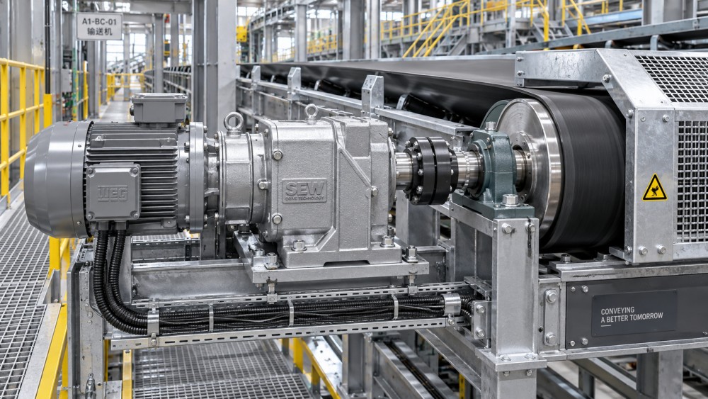
A coaxial gearbox is often the most practical transmission layout when a conveyor or driven machine must fit into a narrow, straight-through envelope. Its input and output shafts share the same centerline, allowing the motor, gearbox, coupling, and driven shaft to be arranged in one axial path rather than offset around the equipment. That geometry can reduce side clearance requirements, simplify guarding, and avoid the structural compromises created by parallel-shaft or right-angle arrangements.
For a space-limited conveyor, however, compactness alone is not the decision criterion. The gearbox must still deliver the required torque through starting, loaded running, stopping, and possible upset conditions; tolerate the conveyor’s alignment and structural movement; allow access for lubrication and inspection; and integrate with the chosen motor, brake, backstop, coupling, and control system. A coaxial gearbox suits the application when its inline form solves a genuine layout constraint without transferring hidden maintenance or load risks to another part of the system.
Why shaft alignment changes the whole drive layout
In a coaxial gearbox, power enters and exits along a common axis. Internally, the reduction may use helical, planetary, or other concentric gear arrangements, but the installation consequence is the same: the drive train remains linear. This differs from a parallel-shaft gearbox, where the output shaft is laterally displaced from the motor axis, and from a bevel or worm gearbox, where the output commonly turns through 90 degrees.
On a conveyor, an offset gearbox can force the motor package to project beside the frame, into an aisle, service zone, or equipment envelope. It may also require a more complicated baseplate, a jackshaft arrangement, or additional coupling components to connect the reducer to the drive pulley. These are not always poor solutions; some are essential where the driven shaft direction must change. But where the conveyor head shaft and motor can be placed on the same axis, an inline gearbox removes a source of geometric complexity.
This matters especially at transfer points, under elevated galleries, inside compact processing skids, beneath hopper structures, and in enclosed material-handling lines where access routes must remain clear. The available volume around a conveyor drive is rarely empty. It competes with chutes, guards, inspection doors, structural steel, electrical trays, dust-control ducting, walkways, and lifting access. A drive that stays close to the conveyor centerline can make those interfaces easier to resolve.
There is an important distinction between a short drive package and a narrow drive package. A coaxial reducer may minimize lateral projection but can add axial length, particularly when a motor, brake, flexible coupling, and torque arm are included. The usable question is therefore not whether the gearbox is “compact” in catalog terms. It is whether its total installed envelope fits the actual clearance available in the direction that matters.
Where the coaxial arrangement is most useful
Inline reduction is well suited to conveyors whose drive pulley shaft is accessible from the end of the frame and where the motor can extend along the line of the shaft. Belt conveyors with end-mounted drives are a common example. Depending on the mounting method, the reducer can connect through a hollow output shaft, a shrink disc, a keyed coupling, or a separate coupling arrangement. The selected connection affects not only installation length but also how torque is transmitted and how easily the drive can be removed.
Chain conveyors, roller conveyors, screw conveyors, bucket elevators, and compact process machines can also benefit where their driven shaft lies in the same practical direction as the motor. In these systems, the design advantage is often not a smaller gearbox body; it is the ability to eliminate an intermediate shaft, reduce the number of bearing-supported rotating elements, or avoid routing power around an obstruction.
For modular conveyor lines, a coaxial layout can make repeated drive stations easier to standardize. A consistent centerline height and mounting interface can simplify frame design, guarding dimensions, cable routing, and spare-part planning. Standardization should not be confused with automatic interchangeability, though. Output torque, service factor, mounting position, shaft diameter, reaction loads, and motor-control requirements still need review for each station.
Space restrictions alone do not make a coaxial gearbox the correct choice. A right-angle gearbox may be better when the motor must sit above, below, or beside the conveyor to preserve end access. A shaft-mounted parallel-shaft reducer can be preferable where an inline motor would extend into a walkway or where the conveyor head arrangement cannot accommodate the added axial length. The suitable layout is the one that preserves required access and structural clearance after all components—not just the gearbox—are installed.
Torque capacity must be checked against conveyor duty, not motor power alone
A frequent selection error is to start with motor power and reduction ratio, then treat the reducer as an interchangeable speed-reduction device. Conveyor loads are more demanding than this approach suggests. The gearbox must be evaluated against output torque, starting torque, duty cycle, inertia, transient loading, ambient temperature, and the nature of the conveyed material.
A lightly loaded roller conveyor may have modest starting requirements. A long belt conveyor with material resting on the belt, a steep inclined conveyor, or a conveyor handling bulk material can impose substantially higher torque during acceleration or restart. If a conveyor can stall, plug, reverse, or receive shock loading from upstream equipment, the project team should define those events before selecting the reducer. A gearbox sized only for steady-state running torque may have inadequate margin during the conditions that produce damage.
The basic relationship remains useful:
Output torque = input torque × reduction ratio × transmission efficiency.
But this is only a starting point. Motor torque varies with motor type, speed, starting method, and variable-frequency drive settings. Output torque requirements vary with belt tension, friction, material mass, conveyor slope, pulley diameter, acceleration time, and resistance from related equipment. The selected gearbox must have a permissible output torque and thermal capacity appropriate to the intended operating condition, with the manufacturer’s published ratings interpreted for the actual mounting position and service conditions.
Where a variable-frequency drive is used, low-speed operation needs particular attention. A conveyor may need high torque at low output speed while the gearbox has reduced opportunities to dissipate heat. If the motor is separately cooled, that can protect the motor from low-speed thermal stress, but it does not automatically solve gearbox thermal limits. The reducer’s oil temperature, housing ventilation, ambient conditions, and operating cycle remain relevant.
The drive connection can determine whether the layout remains compact
Coaxial gearboxes are available with solid shafts, hollow shafts, flange outputs, and integrated mounting arrangements. The preferred option depends on the conveyor structure and the required maintenance method.
A hollow-shaft reducer mounted directly on the driven shaft can remove a coupling and reduce the number of parts that require alignment. It can be an efficient solution for a head pulley shaft or screw conveyor shaft, provided the shaft, keyway or shrink-disc interface, and support arrangement are designed for the transmitted torque. The housing usually requires a torque arm or another reaction arrangement to prevent rotation. That torque arm must accommodate normal structural movement without creating a binding load path.
A solid-shaft gearbox with flexible couplings may require more axial space, but it can offer clearer separation between the gearbox and conveyor shaft. This may be useful where the gearbox must be removed without disturbing the pulley shaft, or where alignment adjustment is expected during installation. It also introduces coupling selection and alignment as critical tasks. A flexible coupling compensates for limited misalignment; it does not justify poor baseplate fabrication, bent shafts, or a structurally unstable conveyor frame.
Direct mounting should not be assumed to eliminate alignment concerns. The driven shaft must remain concentric with the gearbox bore within the installation requirements, and the reducer must not be forced into position by tightening fasteners or drawing it onto a damaged shaft. Excessive installation force, incorrect key fit, or fretting at the shaft interface can turn a compact configuration into a difficult maintenance problem.
Structural movement and reaction loads need early attention
Conveyors are not perfectly rigid. Their frames can deflect under load, expand with temperature changes, and move slightly as belt tension is adjusted. A drive design that looks correct on a static general arrangement drawing may impose unwanted loads on the gearbox when the conveyor operates.
This is especially relevant for shaft-mounted coaxial reducers. The torque arm should restrain housing rotation while allowing the movement expected between the gearbox and the conveyor support. A rigidly constrained arm, incorrectly positioned linkage, or misaligned mounting bracket can introduce side loads into the reducer output connection. The resulting stress may affect bearings, seals, shaft interfaces, or the supporting structure.
Overhung loads also require disciplined review. Sprockets, pulleys, belts, and chain drives mounted on a gearbox output shaft create radial and sometimes axial loading. The allowable load depends on shaft location, load direction, speed, bearing design, and gearbox configuration. A reducer may satisfy torque requirements but still be unsuitable for the imposed overhung load. If external transmission elements are used, their pitch diameter, belt or chain tension, and distance from the gearbox housing should be included in the calculation.
For conveyor drives connected directly to a pulley shaft, the pulley bearing arrangement must carry the belt-induced radial loads independently. The gearbox should transmit torque, not become an unintended structural support for a poorly supported pulley assembly.
Efficiency is an operating issue, not just a catalog figure
Helical coaxial gearboxes are commonly selected where efficient continuous power transmission is important. Their rolling gear contact and multi-stage reduction can provide an efficient route from motor speed to conveyor speed. Yet the installed system efficiency is broader than gearbox efficiency. Coupling losses, belt or chain losses, motor performance, control settings, lubrication condition, and mechanical misalignment all influence the energy actually delivered to the conveyor.
For projects operating many hours, the practical benefit of an efficient drive arrangement is not merely lower energy use. Lower losses also reduce heat generation, which can improve the viability of enclosed installations. A gearbox installed under a cover, near process heat, or within a poorly ventilated machine base has less ability to reject heat. Specifying an inline reducer without reviewing its thermal rating for that enclosure can lead to elevated oil temperature and shortened lubricant life.
Lubricant selection and mounting orientation must match the manufacturer’s requirements. Oil level, breather position, seal exposure, and internal lubrication paths can change when a gearbox is mounted vertically, horizontally, or at an angle. A unit that is correctly rated in one position cannot automatically be used in another simply because the shaft centerline remains convenient.
Maintenance access is the test that layout drawings often miss
A narrow footprint has limited value if routine tasks require dismantling guards, chutes, or adjacent equipment. The project layout should show the actual service envelope for the motor, gearbox, brake, coupling guard, torque arm, and lifting device. It should also identify where technicians can access drain plugs, level plugs, breathers, inspection points, terminal boxes, and fasteners.
Motor replacement is a common overlooked constraint. An inline motor may need to be withdrawn axially. If a wall, transfer chute, handrail, or structural member blocks that path, the apparent installation advantage disappears during maintenance. In some cases, a removable guard section, split support, sliding motor base, or alternative mounting orientation resolves the issue more effectively than changing the gearbox type.
Gearbox removal must be considered separately from motor removal. A shaft-mounted hollow-bore reducer may require clearance to slide off the driven shaft. Corrosion, shaft fretting, or a cramped torque-arm arrangement can make removal far harder than the original installation. Protecting exposed shaft surfaces, specifying appropriate assembly compounds where permitted, and preserving a practical withdrawal path are modest design decisions with large lifecycle consequences.
Control and protection components affect gearbox selection
The gearbox is only one part of the drive system. Conveyors that must resist reverse motion after stopping may need a backstop. Inclined conveyors, lifts, and certain process duties may need a brake capable of holding or controlled stopping. These devices can be integrated into a geared motor package or installed separately, but their torque ratings and installation direction must match the real operating duty.
Soft starters and variable-frequency drives reduce electrical and mechanical shock when correctly configured, yet poor acceleration settings can still create problems. An acceleration time that is too short can demand excessive torque. A time that is too long can leave the gearbox and motor operating in a high-torque, low-speed condition for an extended period. Restart behavior after a process interruption should also be defined: restarting a loaded conveyor is not equivalent to starting an empty one.
For critical conveyors, monitoring can be more valuable than selecting a larger nominal gearbox without a clear failure mechanism in mind. Oil-temperature monitoring, vibration monitoring, motor-current trend review, and regular inspection of seals and torque-arm hardware can reveal developing issues. The appropriate level of monitoring depends on the consequence of downtime, accessibility of the drive, and the predictability of the load.
A practical basis for choosing an inline reducer
A coaxial gearbox is a strong application fit when the driven shaft can be approached axially, lateral clearance is constrained, and the drive package can retain a realistic maintenance envelope. It is particularly effective when direct or near-direct connection removes unnecessary intermediate components without exposing the reducer to unaccounted structural or overhung loads.
The selection should be based on the installed system rather than a reducer catalog page: conveyor resistance and starting conditions, required output speed and torque, motor-control method, output connection, frame movement, mounting orientation, ambient temperature, service access, and protection devices all belong in the same decision. When these conditions are resolved together, the inline geometry of a coaxial gearbox can reduce layout conflict while providing a durable, efficient path for transmitting power to the conveyor or driven machine.
Related News
- How to Assess a Rigid Coupling Supplier for Bore Accuracy and Traceable QualityOct 08, 2026Tribology & Kinematics Expert
- Titanium Alloys Compared: Balancing Strength, Corrosion Resistance, and MachinabilityOct 08, 2026CNC Kinematics Architect
- Where Ductile Iron Dismantling Joints Reduce Alignment Risk in Water PipelinesOct 08, 2026Pipeline Metallurgy Scientist
- Selecting a Precision Bearing Sleeve: Fits, Runout, and Material ChoicesOct 08, 2026Tribology & Kinematics Expert
- Face Milling Cutters: How Insert Geometry Affects Finish on Steel and AluminumOct 08, 2026CNC Kinematics Architect
- Single-Acting Cylinders for Clamping: Stroke, Force, and Return Spring ConsiderationsOct 07, 2026Fluid Power Control Strategist