
Specifying Planetary Gear Units for Tracked Vehicles in High-Torque Drive Systems
A tracked machine can appear well specified on paper and still develop drive-side problems once it reaches steep grades, soft ground, repeated reversing, or long travel cycles. The warning signs are often familiar: travel speed feels inconsistent under load, oil temperature rises during extended operation, seals begin to weep, or a gearbox that looked adequate in a catalog needs attention far earlier than expected. The immediate temptation is to ask for a larger torque rating. That is sometimes necessary, but it is not always the real correction.
The difficult part is that a track drive does not experience one clean, steady load. It sees starting torque, shock from obstacles, braking loads, turning resistance, uneven left-to-right track loading, and periods where the motor continues to deliver high input power while the vehicle moves slowly. When planetary gear units for tracked vehicles are selected only by nominal output torque and reduction ratio, important operating conditions can remain hidden until commissioning or field use.
A more reliable specification begins by treating the final drive as part of a system: hydraulic or electric motor, planetary reduction stage, sprocket, track chain, vehicle mass, undercarriage geometry, duty cycle, mounting structure, and service environment. The aim is not merely to choose a unit that can transmit torque. It is to choose one whose bearing arrangement, gears, housing, seals, lubrication, and interfaces are suited to the actual work the machine is expected to perform.
Start with the operating moment, not the catalog page
Before comparing gearbox models, define the moments when the drive is most stressed. A machine traveling on level, compacted ground may need far less tractive effort than the same machine climbing, pushing, extracting itself from soft material, or turning while carrying an attachment load. Track tension, sprocket engagement, rolling resistance, slope, and payload all influence the torque that reaches the final drive.
It is useful to separate three conditions instead of averaging everything into one number. The first is normal travel: routine movement at expected speed and load. The second is frequent heavy duty: repeated climbing, dozing, drilling support, material handling, or travel through soft terrain. The third is exceptional loading: short-duration shock, obstacle contact, hard braking, track jam conditions, or recovery-related loads. These conditions affect gear tooth loading and bearing reaction differently, and they should be discussed separately with the drive supplier.
Output torque is commonly related to motor torque, total reduction ratio, and transmission efficiency. Yet this simple relationship is only the beginning. A calculation may show enough steady output torque while overlooking peak motor pressure, temporary pressure overshoot, motor displacement changes, or the way a control system applies braking. For electrically driven vehicles, rapid torque response can create similarly sharp transients. The specified unit should therefore be evaluated against both continuous and intermittent torque requirements, with the timing and repetition of peaks made clear.
One useful question during design review is: “What keeps the drive from seeing its highest theoretical torque?” If the answer is a pressure-relief setting, software limit, clutch arrangement, or mechanical shear feature, verify that it is truly effective under the intended operating conditions. If no practical limiting mechanism exists, the gearbox may need to be assessed for a more severe peak-load envelope.
Reduction ratio has consequences beyond travel speed
Reduction ratio is often selected to deliver a desired track speed at a given motor speed. That is reasonable, but an apparently suitable ratio may create problems elsewhere. A lower ratio can demand more motor torque for the same sprocket torque. A higher ratio can improve available output torque, yet it may require the motor to operate at a speed that changes hydraulic flow demand, motor efficiency, heat generation, or controllability at low vehicle speed.
For a tracked vehicle, the ratio also shapes how easily the machine creeps, turns, and holds position. If precision movement is important, consider the interaction between motor displacement, control valve behavior or inverter control, gear reduction, and the small movements needed at the sprocket. A drive system with adequate maximum torque but poor low-speed control can make grading, positioning, pipe handling, or machine alignment more difficult.
The gear ratio should also be checked against braking architecture. Some systems rely on a spring-applied, hydraulically released brake integrated with or mounted near the travel motor. Others use different arrangements. The brake holding torque, gearbox ratio, motor leakage characteristics, and expected parked-load condition must be considered together. A parking brake is not automatically a substitute for confirming whether the mechanical drive can safely resist external load on a slope.
Where many specifications become incomplete: radial and axial loading
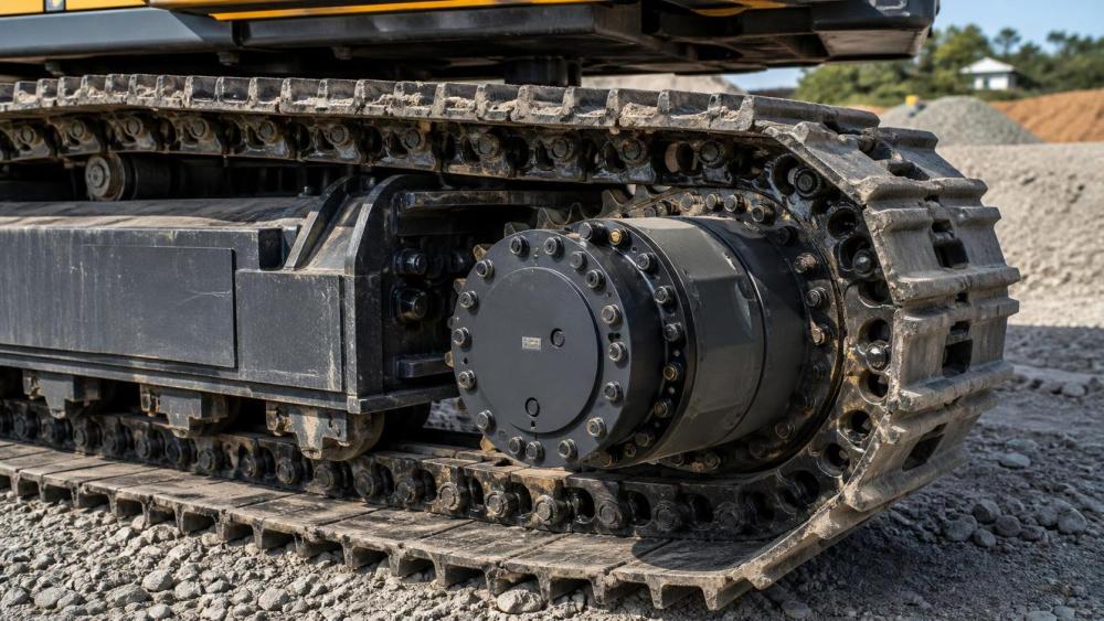
A planetary unit on a tracked machine does more than multiply torque. It supports loads transferred through the sprocket and mounting flange. Track tension produces substantial radial loading. Turning, side slopes, misalignment, frame flexing, and external forces can introduce axial or overturning loads. These are carried by the bearings and housing structure, not by the gear teeth alone.
This is why output bearing capacity deserves the same attention as torque capacity. Ask how the sprocket is supported, where the load path enters the drive, and whether the unit is designed for the expected overhung load. A gearbox with a robust torque rating may still be unsuitable if the sprocket position creates a lever arm that exceeds allowable bearing loading. The mounting face and bolt circle also need to resist transmitted forces without distortion.
Mounting interface details should be released early rather than left for a final packaging check. Confirm the pilot diameter, flange thickness, bolt size and grade requirements, bolt engagement, tightening method, sprocket connection, clearance for assembly tools, and the position of drain, fill, and level ports after installation. A unit can be technically correct but unnecessarily difficult to maintain if the oil level plug is inaccessible or the gearbox cannot be removed without dismantling adjacent structures.
Thermal behavior usually reveals a system issue
High oil temperature is often blamed on the gearbox, although the source may be a combination of factors. High travel resistance raises transmitted torque. An unsuitable ratio may keep the motor in an inefficient region. Excessive internal drag, incorrect lubricant viscosity, low oil level, restricted cooling airflow, or continuous operation near the unit’s thermal limit can all contribute. In hydraulic systems, heat generated upstream also affects the complete drive circuit.
For this reason, obtain the duty cycle in a form that can be evaluated. It should describe running periods, average and peak loads, travel speeds, ambient temperature range, stop-start frequency, expected slopes, and whether the machine spends long periods moving slowly under high tractive effort. A brief maximum torque event and an hour of sustained high-load travel are not equivalent thermal cases.
Lubricant selection should match the gearbox design, temperature range, seal materials, and service plan. Do not assume that a lubricant used elsewhere on the machine is automatically appropriate for the final drive. The viscosity must provide a protective film at operating temperature while remaining workable during cold starts. Contamination control matters as well. Fine debris, water ingress, or incorrect oil mixing can accelerate bearing and gear damage long before a visible failure occurs.
Sealing is an application decision, not a minor accessory
Tracked equipment often works where dust, slurry, water, abrasive fines, washdown, and temperature cycling are normal. A seal arrangement that performs adequately in a sheltered industrial setting may not be enough near a track sprocket. External contamination can damage sealing lips, enter the lubricant, and abrade gear and bearing surfaces. Internal pressure changes caused by heating and cooling can also challenge the sealing system if ventilation is poorly arranged or blocked.
When reviewing planetary gear units for tracked vehicles, describe the exposure honestly. Is the machine used in dry aggregate, wet excavation, tunneling, forestry residue, coastal environments, or wastewater work? Will it be pressure-washed? Could the final drive be temporarily submerged? Is the machine stored outdoors in freezing conditions? These questions help determine whether additional protective features, alternative seal materials, guarded locations, or more frequent inspection intervals are appropriate.
A practical inspection plan should include looking for oil traces around the hub and mounting faces, checking breather condition where applicable, monitoring unusual noise or vibration, and reviewing lubricant condition at the specified service interval. These observations are most useful when recorded from the beginning, because a gradual change is easier to interpret than an isolated inspection after a problem appears.
Use the vehicle architecture to narrow the choices
There is no single “best” planetary drive for every tracked platform. A compact machine with limited installation space may prioritize low envelope dimensions and simple mounting. A larger crawler operating in harsh terrain may require greater bearing capacity, more robust sealing, and stronger tolerance to load reversals. A machine that travels infrequently but performs high-force work may have a different duty pattern from one that spends much of each shift moving over distance.
Instead of asking suppliers for a generic travel gearbox, provide a controlled application package. It should include the proposed sprocket dimensions, track pitch or relevant engagement details, estimated machine mass, center-of-gravity considerations, maximum slope, motor type and displacement or torque-speed curve, operating pressure or electrical limits, desired travel speeds, expected duty cycle, mounting drawing, environmental exposure, and maintenance access constraints. If some values are still provisional, identify them as assumptions rather than presenting them as fixed requirements.
It is also worth clarifying the design boundary between the gearbox and surrounding components. For example, confirm who is responsible for verifying mounting stiffness, bolt preload, motor interface alignment, brake compatibility, and external sprocket loading. Ambiguity at these interfaces can lead to a drive being judged against conditions it was never asked to withstand.
Questions that expose weak assumptions before purchase
During technical review, avoid stopping at “rated torque” and “ratio available.” Ask whether the stated torque is continuous, intermittent, or maximum permissible; what duty cycle was used to establish it; and whether it includes a stated service factor. Request the allowable radial, axial, and overturning loads at the actual sprocket location. Confirm allowable input speed, direction of rotation, acceleration behavior, and whether repeated reversals affect the selection.
For service planning, establish the lubricant type and quantity, initial and routine change intervals, allowable installation orientation, port accessibility, expected inspection points, and recommended response to seal leakage or abnormal noise. Ask what documentation accompanies the unit, such as dimensional drawings, interface information, lubrication instructions, torque guidance, and material or test documentation where required by the purchasing specification.
These questions are not administrative extras. They create a record of the operating assumptions behind the selection. If vehicle mass, motor size, track width, or duty cycle changes during development, the record makes it easier to identify whether the gearbox selection must be revisited.
When a larger unit is not the only answer
If calculations show limited margin, increasing gearbox size may be appropriate, but first locate the governing condition. A different reduction ratio may reduce motor-side demand. A revised sprocket arrangement may improve bearing loading. A control adjustment may limit damaging torque spikes. Better mounting stiffness can reduce misalignment. Improved sealing or a more suitable lubricant may address an environmental risk that extra gear capacity would not solve.
On the other hand, a recurring overload should not be managed only through operating instructions. If the intended work routinely produces severe traction loads, frequent reversals, or high side loads, those conditions belong in the design requirement. Durable tracked drive systems are usually the result of aligning motor capability, planetary reduction, sprocket support, controls, and maintenance access rather than relying on one component to compensate for every uncertainty.
The most dependable selection process is therefore iterative. Establish the real operating envelope, check torque and load paths, review thermal and sealing conditions, verify interfaces, then update the specification when the vehicle design changes. That approach makes planetary gear units for tracked vehicles easier to compare and reduces the chance that a seemingly simple final-drive purchase becomes a late-stage reliability issue.
Related News
- How to Assess a Rigid Coupling Supplier for Bore Accuracy and Traceable QualityOct 08, 2026Tribology & Kinematics Expert
- Titanium Alloys Compared: Balancing Strength, Corrosion Resistance, and MachinabilityOct 08, 2026CNC Kinematics Architect
- Where Ductile Iron Dismantling Joints Reduce Alignment Risk in Water PipelinesOct 08, 2026Pipeline Metallurgy Scientist
- Selecting a Precision Bearing Sleeve: Fits, Runout, and Material ChoicesOct 08, 2026Tribology & Kinematics Expert
- Face Milling Cutters: How Insert Geometry Affects Finish on Steel and AluminumOct 08, 2026CNC Kinematics Architect
- Single-Acting Cylinders for Clamping: Stroke, Force, and Return Spring ConsiderationsOct 07, 2026Fluid Power Control Strategist