
Sizing Large-Diameter Ring Gears for High-Torque Drives: Load, Backlash, and Alignment
Large diameter ring gears in high-torque drives should be sized as part of a complete mesh and support system, not as a diameter-and-module selection exercise. A gear can have adequate nominal tooth capacity yet still fail early because the rim distorts, the pinion is misaligned, backlash disappears during thermal growth, or only one end of the face width carries the load.
For technical evaluators, the practical question is not simply “What gear size is required?” It is: what combination of gear geometry, material, mounting, pinion arrangement, and operating control will keep tooth contact stable under the worst credible load condition? This is particularly important in mills, rotary equipment, slewing systems, mining machinery, heavy handling equipment, and large process drives, where a replacement gear may be expensive and difficult to install.
Start with transmitted tangential load, not torque alone
Drive torque is the starting input, but tooth loading is governed by the tangential force at the pitch circle. For a given torque, a larger pitch diameter reduces tangential force; however, increasing diameter can also make the ring more flexible and more sensitive to mounting runout. The design must therefore balance tooth load against structural stiffness.
The basic relationship is:
Tangential force = transmitted torque / pitch radius
This force is then modified by the conditions the gear will actually see. A slow, steady kiln drive and a reversing bulk-material machine may transmit similar average torque but impose very different demands on the gear mesh. The evaluation should account for:
- Continuous operating torque and speed range.
- Starting torque, stalled-drive torque, and overload events.
- Shock loading from material impact, intermittent engagement, or rapid reversal.
- Load sharing where two or more pinions drive the same ring gear.
- Duty cycle, including whether high torque occurs briefly or for long operating periods.
- External radial or axial loads that may deform the supporting structure.
A common mistake is to apply a service factor to average torque and treat the result as the full design case. That may be insufficient when a motor, gearbox, coupling, or process control system can deliver short-duration peaks that are much higher than normal running demand. At the same time, assuming every theoretical peak is fully transmitted can create an unnecessarily large and costly gear. The useful approach is to define credible load cases with the equipment team: normal running, start-up, upset condition, reversal, and emergency stop.
Tooth strength involves more than choosing a larger module
Module, pressure angle, face width, tooth count, and material condition all influence gear capacity. A larger module generally produces a thicker tooth and is often appropriate for high tangential load, but it does not automatically solve every failure mode. Tooth bending at the root and contact stress at the flank need separate consideration.
Root bending stress is associated with tooth breakage or fatigue cracking. Contact stress is associated with pitting, micropitting, scuffing, or surface distress. A design with a very wide face can lower nominal stress, yet that benefit only exists when the load is distributed across the face. If the ring gear and pinion are not aligned, added face width may simply create unloaded regions while one edge carries excessive force.
Material and heat treatment should follow the expected duty and manufacturing route. Through-hardened or normalized steel may be suitable for some moderate-speed, heavy-duty open gearing applications where repairability and tolerance of local contamination matter. Hardened tooth flanks can support higher contact stress and improved wear resistance, but they demand tighter control of geometry, lubricant cleanliness, and alignment. For segmented large rings, the tooth treatment, joint design, rim stiffness, and machining sequence must be considered together. A strong tooth form does not compensate for a segment joint or mounting flange that permits local movement.
Evaluators should request a design basis that distinguishes the following checks rather than presenting one undifferentiated “gear rating”:
Backlash is an operating clearance, not a machining defect
Backlash is the circumferential clearance between mating tooth flanks. In a high-torque drive, it must be sufficient to prevent interference when components heat up, deflect, or move through their running eccentricity. It must also be controlled tightly enough to avoid excessive impact, torsional noise, and positioning error.
There is no universal backlash value that can be copied from one ring gear to another. The acceptable range depends on pitch size, accuracy grade, thermal growth, gear arrangement, expected runout, bearing clearance, housing rigidity, and whether the machine reverses. A large ring mounted to a warm rotating shell can change center distance relative to a pinion mounted on a separate gearbox foundation. That movement must be included in the assembled condition, not treated as a workshop-only tolerance.
Too little backlash is usually more damaging than evaluators expect. As clearance closes, tooth flanks can run in interference, lubricant film is disrupted, and the mesh may generate heat that further worsens the condition. Excessive backlash is also undesirable, especially in reversing drives: torque changes can produce a repeated flank impact that accelerates wear on the pinion, gear teeth, shafts, and couplings.
Specify backlash together with a measurement condition. The drawing or inspection plan should state whether readings are taken cold, at a defined rotational position, under no load, and at which locations around the circumference. For very large gears, measuring at only one location can conceal pitch variation or eccentric mounting.
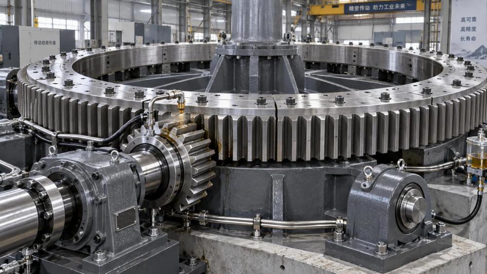
Alignment and runout usually determine whether the rated capacity is achieved
Large diameter ring gears magnify the consequences of small geometric errors. The pinion and ring gear must maintain the intended center distance, shaft parallelism, lead alignment, and tooth contact pattern throughout operation. Errors can originate in the gear itself, but often arise from the surrounding machine: a distorted support frame, worn bearings, loose foundation bolts, eccentric mounting surfaces, or a shell that changes shape with temperature and load.
There are several related conditions to separate during evaluation:
- Radial runout: variation in the effective pitch radius as the ring rotates. It changes backlash around the circumference.
- Axial runout or wobble: side-to-side movement that shifts the mesh across the tooth face.
- Lead misalignment: lack of parallelism between the pinion and ring gear axes, producing edge loading.
- Mounting eccentricity: an off-center gear location relative to the rotating member or reference bore.
- Deflection under torque: elastic movement that may not be visible during unloaded installation checks.
Contact-pattern inspection is valuable because it shows the combined result of these effects. A centered pattern over an appropriate portion of the face width is generally the objective, with allowance for the intended direction of rotation and loaded deflection. A pattern concentrated at one end of the tooth face is not a minor cosmetic issue. It indicates elevated local stress and can lead to pitting, scoring, and localized tooth fatigue even when calculated average stress appears acceptable.
Segmented rings need an assembly-level tolerance plan
Large gears are often manufactured in segments because of transport, machining envelope, and installation constraints. In that case, the interface between segments becomes part of the gear system. Bolt preload, dowel or locating features, joint face condition, machining datum strategy, and installation sequence influence final pitch continuity. A segment that shifts slightly at the joint can create a hard spot that is heard as periodic noise and seen as uneven tooth contact.
The supplier should therefore define inspection of individual segments and inspection after assembly. Evaluating only tooth dimensions before shipment does not demonstrate that the installed ring will meet runout and backlash requirements. For assemblies that cannot be fully trial-fitted at the manufacturing site, installation references and field measurement procedures become especially important.
Mounting stiffness, bearings, and pinion support are part of the gear specification
A ring gear drawing cannot independently guarantee mesh quality. The gear body must be supported by a structure stiff enough to hold its shape, and the pinion shaft must be supported by bearings and a housing that limit movement in the directions that affect contact. Flexible structures may be acceptable if their predictable deflection has been included in the design; they are not acceptable when their movement is unknown or changes with operating condition.
This is why a technical evaluation should include the drive layout. Review the ring gear mounting diameter and fastening method, rim thickness, support spacing, pinion shaft span, bearing arrangement, gearbox attachment, and foundation behavior. In dual-pinion systems, verify how torque is divided and how the system responds when one pinion reaches the tightest backlash point before the other. Equal nominal geometry does not ensure equal load sharing once manufacturing and structural tolerances are present.
Lubrication should match the tooth contact and contamination risk
Lubrication cannot rescue a severely misaligned mesh, but the wrong lubricant can quickly damage a correctly sized gear. Oil systems are often used where enclosure, speed, and cleanliness support controlled film formation. Open gearing may use adhesive, high-load lubricants applied by spray or automated systems. The selection depends on speed, tooth temperature, ambient contamination, access for maintenance, and the gear material and surface condition.
For exposed heavy-duty gears, coverage is more important than simply increasing lubricant quantity. Insufficient coverage permits metal-to-metal contact; excessive application can trap abrasive contamination or obscure developing tooth damage. Inspection should look for changes in contact pattern, polished edge bands, discoloration, scoring, pitting, abnormal debris, and periodic changes around the circumference. These symptoms often point to alignment or runout issues before a tooth fails.
A practical review sequence before release
Technical evaluators can reduce late-stage surprises by reviewing the ring gear in the order the machine will experience it:
- Define torque, speed, duty cycle, starts, reversals, and credible transient loads.
- Establish the gear mesh geometry, then check tooth root and flank capacity for the relevant load cases.
- Review ring body stiffness and the complete mounting arrangement, including segmented joints where used.
- Set backlash as an assembled operating requirement that accounts for runout, thermal movement, and deflection.
- Define allowable alignment conditions and the method for verifying tooth contact after installation.
- Match lubrication, sealing, and inspection access to the operating environment.
- Request material traceability, heat-treatment information where applicable, dimensional inspection records, and an installation measurement plan.
Resources covering gears, gearboxes, bearings, forged shafts, machining tolerances, and industrial lubrication can help teams connect component specifications to the full power-transmission assembly. That system-level view is central to the technical information organized by Global Industrial Machining & Piping Equipment Network (IMPE), particularly where machining capability, inspection practice, and long-term drive reliability must be reviewed together.
The final selection should not be released on tooth capacity alone. A reliable high-torque ring gear is one whose teeth, rim, mounting structure, pinion support, backlash range, and lubrication method remain compatible when the machine is hot, loaded, and operating through its full rotation.
Related News
- Using Industrial Air Blow Guns to Clear Chips Without Spreading DebrisOct 15, 2026Fluid Power Control Strategist
- Ductile Iron Pipe Valves: Which AWWA Standards Apply to Water Main Projects?Oct 15, 2026Dr. Elias Vance
- Why Vacuum Suction Cups Lose Grip on MDF in Woodworking MachinesOct 15, 2026CNC Kinematics Architect
- Choosing a Variable Displacement Piston Pump Manufacturer: What to VerifyOct 15, 2026Fluid Power Control Strategist
- Parallel vs. Angular Pneumatic Grippers for Confined Assembly StationsOct 15, 2026Fluid Power Control Strategist
- Die Castings vs. Investment Castings: Which Costs Less at Your Production Volume?Oct 14, 2026Foundry Phase-Change Fellow