
Planetary Gearbox vs Helical Gearbox: Which Fits High-Torque Equipment?
Planetary Gearbox vs Helical Gearbox: Which Fits High-Torque Equipment?
When evaluating high-torque equipment, the planetary gearbox vs helical gearbox decision affects torque density, efficiency, installation space, load distribution, and long-term reliability. For technical evaluators, the right choice depends on more than rated torque: duty cycle, shock loads, reduction ratio, alignment, lubrication, and maintenance access all matter. This comparison examines where each gearbox design performs best in demanding industrial drive systems.
The question is often framed too narrowly: which gearbox can transmit more torque? In practice, both designs can serve heavy-duty applications. The more useful question is whether the equipment needs very high torque within a compact envelope, or whether it benefits from a flexible, serviceable drive arrangement that can accommodate a broad range of ratios, shaft positions, and mounting layouts.
This distinction matters in conveyors, mixers, crushers, lifting systems, rolling equipment, mining machinery, industrial presses, pump drives, and hydraulic power units. A gearbox that appears acceptable on a basic torque calculation may still be poorly matched to repeated starts, reversing cycles, radial loads, thermal conditions, or the maintenance realities of the installation.
The Fundamental Difference Is Load Path
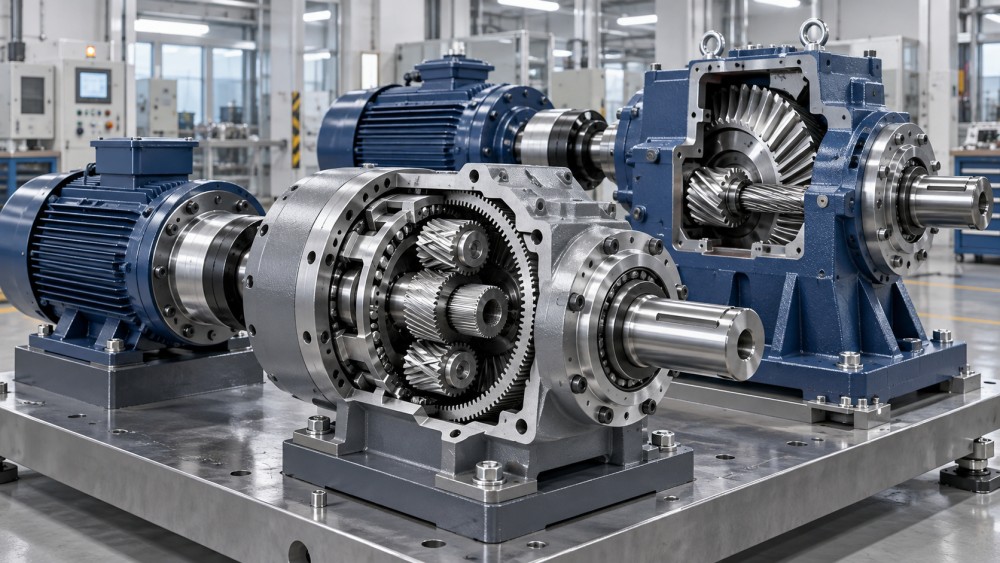
A planetary gearbox uses a central sun gear, multiple planet gears, an outer ring gear, and a planet carrier. Torque is divided among several planet gears rather than being transferred through one primary gear mesh. This shared load path is the reason planetary drives are widely considered when high output torque must be delivered from a relatively small package.
A helical gearbox transfers motion through angled gear teeth. The angled tooth form generally produces smoother engagement than a spur gear arrangement, while allowing substantial load capacity and efficient power transmission. Helical gearboxes may be supplied as inline, parallel-shaft, right-angle, shaft-mounted, or multi-stage units. Their layout flexibility is often as important as their torque capacity.
Neither architecture is automatically superior. A planetary reducer concentrates capability into a compact, coaxial design. A helical reducer provides a familiar and adaptable solution for many continuous-duty industrial drives, especially where physical access, mounting orientation, and motor arrangement influence the overall machine design.
Where Planetary Gearboxes Have a Clear Advantage
Planetary gearboxes are usually strong candidates when torque density is the governing constraint. Because several planet gears can share the transmitted load, a planetary reducer can often achieve high torque capacity without the larger center distance associated with some conventional multi-stage arrangements. This is useful when the gearbox must fit inside a machine frame, wheel hub, rotating assembly, winch drum arrangement, or compact drive module.
The coaxial input and output arrangement is another practical benefit. For equipment requiring a straight-through drive axis, such as certain servo-driven machines, rotary tables, mixers, mobile equipment drives, and compact lifting mechanisms, the layout can simplify mechanical integration. It may also reduce the need for additional couplings or offset transmission elements.
High reduction ratios can be obtained in a compact multi-stage planetary design. That does not eliminate the need to evaluate efficiency, backlash, torsional stiffness, and heat rejection, but it can make the architecture attractive where a motor must operate at a higher speed while the driven machine requires slow, high-torque output.
Planetary gearboxes also deserve consideration in applications with frequent acceleration, deceleration, or directional reversal. The appropriate unit must still be sized for peak torque and inertia effects, but the compact structure and distributed gear loading can suit dynamic systems better than a gearbox selected only for steady-state output torque.
Why Helical Gearboxes Remain a Heavy-Duty Standard
Helical gearboxes remain common across process industries because they provide a practical balance of efficiency, durability, serviceability, and configuration choice. An inline helical unit may be appropriate where a simple motor-to-driven-shaft arrangement is possible. A parallel-shaft or right-angle helical design can be more suitable when the machine layout requires torque to change direction or fit within limited structural clearance.
For belt conveyors, bucket elevators, agitators, fans, pumps, and general material-handling systems, the gearbox is often one component in a larger assembly involving a motor, coupling, baseplate, driven shaft, bearings, and guarding. Helical gearboxes are frequently easier to arrange around these system-level constraints. Their modularity can also help when a machine builder needs related drive sizes across several equipment models.
The smooth tooth engagement of helical gearing supports quieter, more stable operation than simpler spur gear configurations. However, helical gears develop axial thrust, which must be managed by the gearbox bearing system and considered when reviewing shaft loads. A supplier’s catalog torque rating should never be treated as a substitute for checking allowable overhung load, axial load, mounting position, and bearing arrangement.
Where maintenance teams need predictable access to seals, breather locations, oil inspection points, and shaft-mounted interfaces, a conventional helical gearbox may offer practical advantages. This is not a universal rule; design quality varies by manufacturer. Still, accessibility is frequently underestimated during project selection and becomes visible only after the drive is installed above a conveyor, behind guarding, or in a contaminated process area.
A Decision Comparison for High-Torque Applications
The table is a screening tool, not a final selection method. Gear geometry, housing stiffness, bearing capacity, heat treatment, surface finish, lubrication method, and manufacturing tolerances determine whether a specific gearbox delivers its intended service life. Two units with similar nominal torque ratings may behave very differently under shock loads or poor alignment.
Do Not Size from Rated Torque Alone
High-torque equipment usually produces more than one torque value. There may be continuous operating torque, starting torque, emergency-stop torque, breakaway torque, occasional overload torque, and torque caused by jammed material or process upset. The gearbox should be evaluated against the actual load spectrum, not merely the motor nameplate or the machine’s average demand.
A crusher, screw conveyor, mixer, or heavy-duty valve actuator may see short-duration peaks that are far above normal running torque. In a lifting or indexing system, reflected inertia and braking events can be equally important. Where a variable-frequency drive or servo system is used, the speed profile and control settings should be reviewed with the drivetrain rather than treated as separate electrical details.
Technical evaluators should also distinguish between gearbox output torque and the loading at the output shaft. A sprocket, pulley, chain drive, or external pinion can create radial and axial forces that affect shaft and bearing life. Misalignment in couplings, flexible foundations, distorted baseplates, or thermal movement can create loads not visible in a simple torque calculation.
Key information to confirm before release
- Required output speed, continuous torque, peak torque, and expected duty cycle.
- Starting frequency, reversing requirements, load inertia, and braking method.
- Mounting orientation, available installation envelope, and input/output shaft arrangement.
- External radial and axial loads from couplings, chains, belts, pulleys, or driven elements.
- Ambient temperature, dust, moisture, washdown exposure, and lubricant operating conditions.
- Inspection access, lubricant change requirements, seal replacement access, and downtime constraints.
Efficiency, Heat, and Lubrication Are Linked
Both planetary and helical gearboxes can provide efficient mechanical transmission when properly designed and maintained. Yet efficiency should be assessed at the intended ratio, speed, load, and temperature. Losses become heat, and heat affects lubricant viscosity, seal condition, bearing performance, and gear contact behavior.
A compact planetary reducer may be attractive for its power density, but compactness also makes thermal management a design question. If a drive operates continuously at high torque in a warm enclosure, the evaluator should confirm the permitted thermal rating, lubrication arrangement, cooling options if applicable, and whether the selected mounting position affects oil distribution.
Helical units face similar concerns, particularly in multi-stage arrangements or installations with limited airflow. Oil level, breather location, lubricant type, contamination control, and sealing selection should match the environment. In mining, cement handling, wastewater infrastructure, and outdoor materials processing, dust and moisture control are often just as consequential as gear sizing.
Manufacturing Quality Appears in the Details
For critical drives, gearbox selection should extend beyond the catalog page. Gear material, case hardening or other heat-treatment routes, tooth finishing, carrier construction, bearing brand or specification, housing machining accuracy, and inspection documentation all influence consistency. A planetary design depends on effective load sharing; deviations in gear geometry, carrier alignment, or bearing support can reduce the benefit of having multiple planet gears.
Helical gearboxes likewise depend on controlled tooth contact and reliable bearing support. Gear tooth quality alone cannot compensate for a housing that allows misalignment under load or an output shaft arrangement that is unsuitable for the attached pulley or sprocket.
This is where a broader power-transmission review is valuable. IMPE organizes information across gears, bearings, shafts, couplings, seals, lubrication systems, cast housings, forged components, and machining capability because gearbox reliability rarely belongs to one component alone. The strongest selection process connects the reducer to the actual machine structure and operating environment.
Choosing the Better Fit
Choose a planetary gearbox when the application needs high torque in a compact, coaxial package; when reduction must be achieved without consuming excessive space; or when dynamic operating conditions make torque density and torsional behavior especially relevant. Typical examples include compact winches, rotary machinery, mobile equipment drives, high-torque servo applications, and space-constrained heavy machinery assemblies.
Choose a helical gearbox when installation geometry, shaft orientation, modularity, continuous operation, or maintenance access drive the decision. It is often the more natural fit for conveyor systems, process equipment, pumps, mixers, and industrial machinery where the reducer must integrate with an established mechanical layout rather than occupy the smallest possible envelope.
For a planetary gearbox vs helical gearbox comparison, the final decision should be made after reviewing the load spectrum, external shaft forces, reduction requirement, thermal environment, mounting details, lubrication plan, and documentation expected from the supplier. Rated torque starts the discussion. The real selection is completed when the gearbox, motor, coupling, driven load, and maintenance conditions have been assessed as one drive system.
Related News
- How to Assess a Rigid Coupling Supplier for Bore Accuracy and Traceable QualityOct 08, 2026Tribology & Kinematics Expert
- Titanium Alloys Compared: Balancing Strength, Corrosion Resistance, and MachinabilityOct 08, 2026CNC Kinematics Architect
- Where Ductile Iron Dismantling Joints Reduce Alignment Risk in Water PipelinesOct 08, 2026Pipeline Metallurgy Scientist
- Selecting a Precision Bearing Sleeve: Fits, Runout, and Material ChoicesOct 08, 2026Tribology & Kinematics Expert
- Face Milling Cutters: How Insert Geometry Affects Finish on Steel and AluminumOct 08, 2026CNC Kinematics Architect
- Single-Acting Cylinders for Clamping: Stroke, Force, and Return Spring ConsiderationsOct 07, 2026Fluid Power Control Strategist