
How to Size Worm Gear Reducers for Packaging Machines Without Overloading
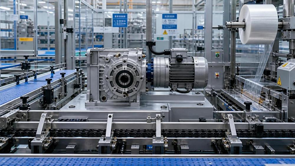
On a packaging line, overload rarely announces itself politely. It shows up as rising gearbox temperature, erratic starts, slower indexing, seal leakage, or a reducer that fails much earlier than the maintenance schedule suggested. In many cases, the root cause is not poor workmanship but poor sizing. Choosing worm gear reducers for packaging machines is less about reading a catalog torque number and more about understanding what the machine actually asks the drive to do every minute of the shift.
For technical evaluators, that distinction matters. A reducer that survives on paper may still struggle in real production if the conveyor is heavily loaded at startup, if the infeed sees frequent jams, or if the wrapping section cycles constantly with abrupt acceleration and deceleration. Proper sizing means translating machine behavior into torque, duty, and thermal demands, then checking whether the reducer can handle those demands without being pushed into overload.
Why packaging applications can be deceptively hard on worm reducers
Packaging machines are often perceived as moderate-duty systems because many operate at relatively low horsepower. But low motor power does not automatically mean low reducer stress. Worm gearboxes in cartoners, case erectors, labelers, film wrappers, palletizing subsystems, and indexing conveyors may see repeated starts, uneven product flow, intermittent shock loads, and long operating hours. These conditions can be harder on the gearbox than a steady-state application with a higher nominal power rating.
Worm gear reducers are still widely selected because they are compact, quiet, cost-effective, and well suited to applications requiring speed reduction in a small footprint. They can also provide smooth motion and useful right-angle power transmission, both valuable in dense packaging equipment layouts. The sizing challenge comes from their operating characteristics: compared with some other gearbox types, worm reducers can generate more heat and may have lower efficiency, especially at certain ratios and load conditions. That means overload risk is not only about tooth strength. It is also about thermal capacity and real operating cycle.
Start with the machine, not the gearbox catalog
A reliable sizing exercise begins with the load profile of the packaging machine. Before comparing reducer models, collect the application inputs that define what the gearbox will experience in service:
- Motor power and motor speed
- Required output speed
- Required output torque at normal running condition
- Startup frequency and acceleration time
- Duty cycle: continuous, intermittent, indexing, or reversing
- Load type: uniform, moderate shock, or heavy shock
- Hours of operation per day
- Ambient temperature and ventilation around the reducer
- Mounting position and lubrication implications
- Any abnormal events such as jams, backpressure, or product accumulation
This is the part many teams rush. Yet in packaging, the difference between a continuously loaded outfeed conveyor and an intermittently indexing sealing head is substantial. Two applications may use the same motor size, but the reducer requirement can be very different because the torque peaks, stop-start behavior, and thermal conditions are different.
Calculate torque demand in a way that reflects reality
The basic calculation is straightforward: output torque is derived from motor power, reducer ratio, and efficiency. But for worm gear reducers for packaging machines, the real question is not only nominal torque. You need to know the peak torque, the recurring torque, and the torque during upset conditions.
As a practical approach, separate torque demand into three layers:
- Running torque: the torque needed once the machine is at stable operating speed.
- Acceleration torque: the extra torque required to bring inertia up to speed during starts or indexing.
- Disturbance torque: the temporary torque spikes caused by product bunching, film tension variation, misfeeds, or mechanical binding.
If the machine indexes, acceleration torque can dominate. If the conveyor occasionally backs up with product, disturbance torque may be the factor that determines whether the reducer survives. A common mistake is to size only against running torque, then assume the service factor will quietly absorb everything else. Sometimes it will. Often it will not.
For evaluators working across OEM or plant projects, it helps to ask the machine designer a blunt question: “What is the worst repeatable load event this reducer will see?” That answer is usually more revealing than the rated motor nameplate alone.
Service factor is not a formality
Once nominal torque is known, service factor becomes the bridge between ideal calculations and production reality. For packaging machinery, service factor selection should reflect duty severity, daily operating hours, shock level, and whether the machine starts under load. A worm reducer sized too close to its nominal rating may run acceptably during commissioning yet drift into thermal stress or wear issues after long production runs.
Technical evaluators should avoid two extremes. One is ignoring service factor and choosing by catalog torque alone. The other is applying an overly conservative factor without understanding the actual duty cycle, which can push the design toward unnecessary size, cost, and efficiency penalties. The goal is not to maximize gearbox size. It is to match the reducer to the machine’s true load spectrum.
In packaging lines, the following situations generally justify more caution:
- Frequent starts and stops
- Indexing motion with short dwell times
- Product accumulation causing intermittent overload
- Sudden directional changes or reversing duty
- Long daily operation with limited cooling airflow
- Applications where line downtime is especially expensive
Do not ignore thermal rating and efficiency
With worm gear reducers, mechanical torque capacity and thermal capacity are not always the same thing. A reducer may be strong enough to transmit the required torque, yet still overheat because the application runs continuously and the generated heat cannot dissipate fast enough. This is especially important in enclosed packaging equipment, washdown-adjacent areas with shielding, or compact machine frames where airflow is poor.
Because worm gearing can have lower efficiency than helical or bevel-helical alternatives, more input energy may turn into heat. Higher ratios, continuous duty, and sustained load intensify that issue. For this reason, sizing should always include a thermal check, not just a strength check.
Ask these questions during evaluation:
- Is the reducer’s thermal rating adequate for the actual operating hours?
- Does the selected ratio reduce efficiency enough to create heat problems?
- Will the ambient temperature or enclosure design trap heat?
- Is external cooling or a different gearbox style worth considering?
If a worm reducer is operating near thermal limits, apparent overload symptoms can emerge even when torque calculations look acceptable. Oil degradation, seal hardening, and faster wear often follow.
Ratio selection affects more than output speed
It is tempting to choose ratio based only on required output rpm, but ratio also influences torque multiplication, efficiency, and backdriving behavior. In packaging systems, a very high ratio may help meet low-speed requirements in a compact package, yet it can also increase heat generation and reduce overall drive efficiency. A lower ratio paired with a different motor speed, VFD tuning, or alternate drive arrangement may perform better over time.
For technical reviewers, this is where system-level thinking matters. The reducer is only one part of the drive train. Motor selection, control method, load inertia, and machine motion profile all shape what the reducer experiences. When worm gear reducers for packaging machines are evaluated in isolation, overload risk is easier to miss.
Account for startup behavior and inertia
Many overload complaints originate at startup. A conveyor that is easy to run once moving may still demand a high breakaway torque when loaded with cartons, containers, or bundled product. An indexing star wheel or rotary station can impose sharp inertia-related peaks each cycle. If the motor and reducer combination is tuned for aggressive acceleration to maximize throughput, those peaks become even more relevant.
This is why inertia matching deserves attention. High reflected inertia can create repeated torque spikes that shorten gear life even if average load seems moderate. Soft starts, VFD ramp adjustments, servo profile refinement, or mechanical changes such as flywheels and coupling selection can reduce those spikes. In some cases, the right answer is not a larger reducer but a better motion profile.
Mounting position, lubrication, and orientation are part of sizing
Reducers do not behave identically in every position. Mounting orientation affects lubrication distribution, seal exposure, and heat dissipation. In compact packaging equipment, reducers may be mounted vertically, sideways, or in awkward positions to fit the frame. If lubrication is not adequate for that orientation, overload-like symptoms can appear because the gears and bearings are not receiving the oil film they need.
Evaluators should verify that the selected worm reducer is approved for the intended mounting position and that the lubrication method matches the duty cycle. This is particularly relevant for continuous operation, elevated ambient temperatures, or applications with frequent cycling.
When a worm reducer may not be the best answer
Worm reducers remain useful and widely applied, but they are not automatically the best choice for every packaging machine. If the application demands very high efficiency, frequent reversing, low heat generation, or sustained heavy-duty torque, another gearbox type may offer more operating margin. Helical-bevel or inline helical solutions can sometimes reduce thermal stress and improve lifecycle economics, even if initial size or cost differs.
This does not weaken the case for worm gearing. It simply reminds buyers and engineers that good sizing starts with application reality, not component habit. On mature production lines, many recurring reducer failures are really architecture mismatches that were never revisited.
A practical evaluation checklist for technical decision-makers
Before approving a reducer, it helps to pause and review the selection against a short but disciplined checklist:
- Does rated output torque exceed actual running and peak demand with an appropriate service factor?
- Has acceleration torque been included, especially for indexing or frequent-start machines?
- Has thermal capacity been checked for ambient conditions and operating hours?
- Is reducer efficiency acceptable for the selected ratio and duty cycle?
- Can the reducer tolerate shock loads, jams, and product accumulation events?
- Is the mounting position approved, and is lubrication suitable for that orientation?
- Are shaft, coupling, and driven component loads within allowable limits?
- Would a different gearbox type reduce overload risk or improve lifecycle performance?
These questions are simple, but they force the selection process out of catalog-only thinking and into application engineering.
Where better supplier information improves sizing accuracy
In industrial procurement, the quality of technical information often determines the quality of the final selection. A reducer supplier that provides only ratio and nominal torque leaves too many risks unexamined. Better evaluation depends on structured data: thermal ratings, efficiency ranges, allowable overhung loads, lubrication guidance, mounting constraints, and duty-related selection notes.
This is where industrial information platforms such as IMPE can be useful in the broader decision process. For buyers comparing power transmission components, the value is not in marketing language but in understanding how load rating, lubrication, sealing, alignment, and long-term operating conditions affect uptime. In packaging machinery, that clarity can prevent a reducer from being selected on incomplete assumptions.
The safer way to size for uptime
If there is one principle worth keeping in mind, it is this: worm gear reducers for packaging machines should be sized for the work the machine actually does, not the work it appears to do at a glance. Packaging equipment often looks light, clean, and orderly, but the reducer experiences every startup, every product surge, every jam, and every hour of continuous operation.
A well-sized reducer does not merely avoid failure. It helps the machine run cooler, more consistently, and with less maintenance disruption. For technical evaluators, that outcome comes from disciplined load assessment, realistic service factor selection, thermal verification, and a willingness to question whether the chosen reducer type truly fits the duty. That is how overload is prevented before the line ever starts.
Related News
- How to Assess a Rigid Coupling Supplier for Bore Accuracy and Traceable QualityOct 08, 2026Tribology & Kinematics Expert
- Titanium Alloys Compared: Balancing Strength, Corrosion Resistance, and MachinabilityOct 08, 2026CNC Kinematics Architect
- Where Ductile Iron Dismantling Joints Reduce Alignment Risk in Water PipelinesOct 08, 2026Pipeline Metallurgy Scientist
- Selecting a Precision Bearing Sleeve: Fits, Runout, and Material ChoicesOct 08, 2026Tribology & Kinematics Expert
- Face Milling Cutters: How Insert Geometry Affects Finish on Steel and AluminumOct 08, 2026CNC Kinematics Architect
- Single-Acting Cylinders for Clamping: Stroke, Force, and Return Spring ConsiderationsOct 07, 2026Fluid Power Control Strategist