
Gear Motors for Conveyors: Matching Torque, Duty Cycle, and Energy Use
Gear Motors for Conveyors: Matching Torque, Duty Cycle, and Energy Use
Selecting gear motors for conveyors requires more than matching a target belt speed with a catalog output power. A conveyor can appear straightforward on a layout drawing, yet its drive system must handle starting resistance, changing material loads, incline forces, stop-start operation, ambient conditions, and the mechanical condition of the conveyor itself. A motor that looks adequate at nominal load may overheat during frequent starts, struggle after material buildup, or consume more energy than expected during long operating hours.
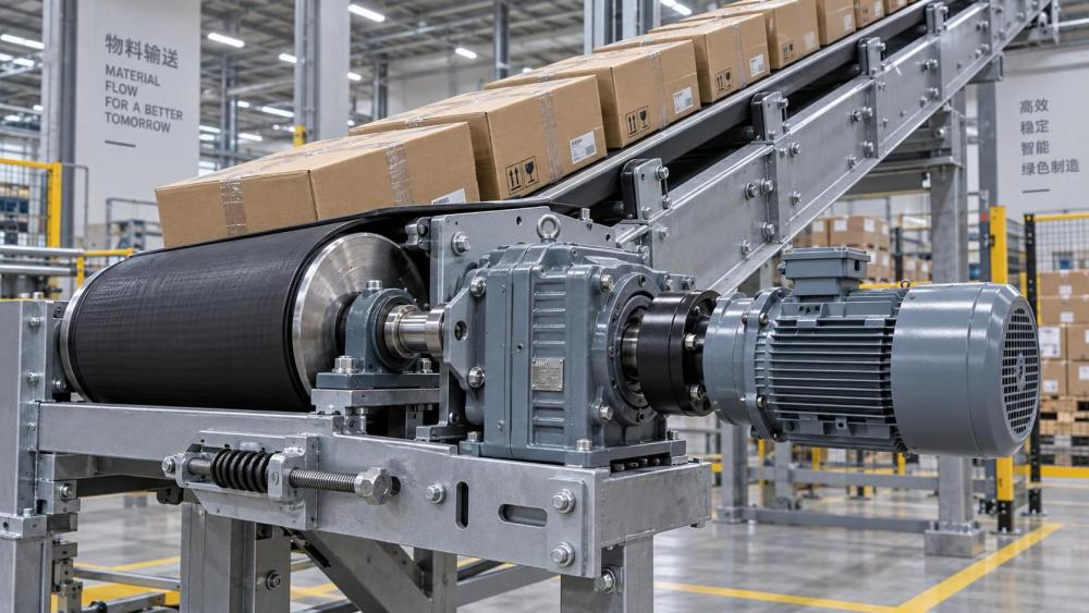
For technical evaluators, the useful question is not simply “What motor size is needed?” It is whether the complete drive assembly can provide the required torque at the driven pulley, through the real duty cycle, without introducing avoidable energy loss or maintenance exposure. That calls for a system view: motor, gearbox, coupling or hollow-shaft connection, pulley, bearings, belt or chain, controls, and the conveyed material all affect the final result.
This is especially relevant in material handling lines, aggregate operations, packaging plants, recycling systems, mining equipment, warehouses, municipal facilities, and process industries. The same gear motor arrangement is rarely appropriate for every application. A lightly loaded horizontal roller conveyor and a high-inertia inclined belt conveyor may have similar output speed requirements but very different torque, thermal, and control demands.
Start with the load at the conveyor, not the motor nameplate
The selection process should begin at the driven element. For a belt conveyor, this is usually the head pulley; for a chain conveyor, it may be the drive sprocket; for roller conveyors, the calculation depends on the transmission arrangement and the number of powered zones. The required output torque is linked to the tangential force needed to move the conveyor and its load, multiplied by the effective drive radius.
In simplified terms, torque at the pulley can be expressed as:
Required torque = tangential force × pulley radius
The tangential force should account for more than the product weight. It may include belt friction, idler resistance, chain drag, material acceleration, slope resistance, skirt friction, scraper contact, and any process-related resistance. A horizontal conveyor with clean rollers may require modest running torque, while a conveyor handling wet bulk material or operating with belt cleaners can have considerably higher resistance. The design calculation should also consider what happens when the line starts fully loaded rather than empty.
Output speed matters because mechanical power is a function of torque and rotational speed. A low-speed conveyor does not automatically need a small motor. If the driven pulley must develop high torque at low revolutions, the gearbox reduction and motor rating must be selected together. Evaluators should avoid comparing units only by kilowatt rating. Two gear motors with the same nominal motor power can have different available output torque, reduction ratios, efficiencies, service capabilities, and allowable radial loads.
Running torque is not starting torque
A conveyor drive often experiences its highest torque demand during startup. The motor must overcome static friction and accelerate rotating components such as pulleys, gear stages, couplings, chains, and the conveyed load. This distinction becomes more important where the conveyor has a long belt, a large pulley diameter, a high material mass, or a tendency for material to settle during shutdown.
A nominal gearbox output torque value should therefore be treated as one selection input, not proof that the drive will start reliably. The supplier’s torque-speed characteristics, starting method, overload capacity, inertia limits, and thermal rating should be checked against the application. Direct-on-line starting, soft starters, and variable frequency drives can produce very different acceleration behavior. A VFD can offer controlled ramp-up and speed adjustment, but it does not remove the need to confirm that adequate torque is available across the required speed range.
There is also a practical trade-off. Excessively aggressive acceleration may create belt slip, shock loads, product instability, or stress on shafts and couplings. An undersized drive may start slowly, trip protection devices, or repeatedly operate in a high-current condition. The goal is not maximum starting torque in isolation; it is controlled acceleration with sufficient margin for expected operating conditions.
Inclines, declines, and the question of backdriving
Inclined conveyors deserve separate attention because gravity becomes a direct part of the load calculation. An uphill conveyor needs additional torque to lift material. A downhill conveyor can become an overhauling load, meaning the conveyed material tends to drive the conveyor rather than being driven by it. In that situation, the selection may involve braking, holding, regenerative considerations, or a gearbox arrangement suitable for the direction and magnitude of the load.
It is unsafe to assume that a gear reducer will hold a loaded incline after power loss. Whether backdriving can occur depends on gearbox type, ratio, friction, load condition, and installation details. Where stopping position or rollback prevention is critical, the project team should specify the required brake or holding function and verify it against the actual load case. This is a design decision that should not be left to catalog interpretation alone.
Duty cycle determines the thermal reality
A gear motor can be mechanically capable of transmitting a certain torque while still being unsuitable for the thermal demands of the application. Heat is generated in the motor and gearbox through electrical losses, gear meshing, bearing friction, lubricant churning, and seals. If the assembly runs continuously at a demanding load, or repeatedly starts and stops without enough cooling time, internal temperatures can rise beyond the intended operating range.
Duty cycle should be documented in practical terms: hours of operation per day, percentage of time running, number of starts per hour, acceleration duration, loaded versus unloaded starts, reversals, ambient temperature, and ventilation around the drive. A conveyor that runs continuously at a steady load may be easier to size than one that cycles rapidly, reverses frequently, and starts with a full accumulation zone. The second system can impose a more severe thermal and mechanical duty even if its average daily throughput is lower.
Service factors are commonly used to reflect operating severity, but they should not become a shortcut for incomplete engineering. A generic multiplier cannot fully represent unusual conditions such as high shock loads, severe contamination, unusually large inertia, or poorly controlled loading. It is better to describe those conditions explicitly when requesting a selection review.
Energy use: look beyond motor efficiency
Energy consumption is shaped by the entire power path. Input electrical power must cover the useful mechanical work at the conveyor plus losses in the motor, gearbox, bearings, belt system, and controls. Selecting a more efficient motor can be worthwhile, but it will not correct persistent belt misalignment, overloaded idlers, poor lubrication, excessive chain tension, or a gearbox ratio that forces the motor to operate outside its useful range.
Gearbox type matters because transmission efficiency differs by design, ratio, load, lubrication condition, and operating speed. Helical, bevel-helical, planetary, and worm arrangements each have different packaging and performance characteristics. Worm gear solutions may be attractive where compact right-angle layouts are needed, but evaluators should carefully examine their efficiency and thermal behavior in continuous-duty applications. There is no universally superior gearbox architecture; the best choice depends on load direction, required reduction, installation geometry, maintenance access, and operating profile.
A VFD may reduce energy use when the process genuinely benefits from speed variation. For example, matching conveyor speed to upstream production flow can avoid unnecessary running at full speed. However, fitting a VFD to a conveyor that must run at one fixed speed does not automatically create major savings. It introduces other questions: low-speed motor cooling, harmonic considerations, control integration, torque behavior, and whether the gearbox and driven system are suitable for the intended speed range.
The gearbox is also a mechanical interface
Gear motor selection is often treated as an electrical sizing exercise, yet installation details can decide whether a correctly sized unit survives. Hollow-shaft drives, shaft-mounted reducers, foot-mounted arrangements, flange-mounted units, and torque-arm configurations place loads into the system differently. The driven shaft diameter, keyway, shrink-disc interface, mounting rigidity, and alignment need to be compatible with the selected arrangement.
Overhung loads deserve attention where sprockets, pulleys, or belt drives are mounted on the gearbox output shaft. Bearing capacity may become the limiting factor even when rated output torque appears sufficient. Coupling alignment is equally important for separate motor and reducer assemblies. Misalignment can add vibration and bearing load, while a flexible coupling selected without considering torque, speed, torsional behavior, and environmental exposure may become the weakest part of the drive train.
Material and manufacturing quality have a direct connection to this issue. Gear hardness, tooth geometry, shaft finish, bearing arrangement, housing stiffness, seal design, and machining accuracy influence noise, heat, vibration, and operating life. For buyers reviewing gearbox suppliers, drawings and rating tables should be accompanied by useful manufacturing and inspection information where the project requires it. In demanding installations, the ability to discuss shafts, cast housings, forged components, lubrication, and assembly tolerances is often more valuable than a broad but shallow product list.
A practical selection brief prevents costly assumptions
Before comparing conveyor gear motors, prepare a concise application brief. It should include conveyor type and layout, pulley or sprocket dimensions, target speed, conveyed material, empty and maximum loaded conditions, incline angle, operating cycle, starts and reversals, ambient environment, available power supply, installation orientation, control method, and any braking requirement. If drawings exist, include shaft and mounting details. If the conveyor is replacing an existing unit, record the actual failure mode rather than simply duplicating the old nameplate.
This approach is aligned with the broader power-transmission evaluation work covered by Global Industrial Machining & Piping Equipment Network (IMPE). Conveyor reliability does not sit within one component category. It depends on how gears, gearboxes, bearings, shafts, pulleys, couplings, lubrication, cast or machined housings, and control equipment work together. Structured technical information helps procurement and engineering teams separate critical requirements from assumptions inherited from older installations.
The final decision should document the selected output torque, speed, reduction ratio, motor power, duty basis, starting method, environmental protection, mounting arrangement, and maintenance provisions. It should also identify what remains to be confirmed: local electrical requirements, site temperature, washdown exposure, spare-parts strategy, or the conveyor manufacturer’s shaft-load limits. A gear motor is not selected successfully because its catalog value matches a calculated number. It is selected successfully when it can start, run, stop, and remain serviceable under the actual conditions the conveyor will face.
Related News
- How to Assess a Rigid Coupling Supplier for Bore Accuracy and Traceable QualityOct 08, 2026Tribology & Kinematics Expert
- Titanium Alloys Compared: Balancing Strength, Corrosion Resistance, and MachinabilityOct 08, 2026CNC Kinematics Architect
- Where Ductile Iron Dismantling Joints Reduce Alignment Risk in Water PipelinesOct 08, 2026Pipeline Metallurgy Scientist
- Selecting a Precision Bearing Sleeve: Fits, Runout, and Material ChoicesOct 08, 2026Tribology & Kinematics Expert
- Face Milling Cutters: How Insert Geometry Affects Finish on Steel and AluminumOct 08, 2026CNC Kinematics Architect
- Single-Acting Cylinders for Clamping: Stroke, Force, and Return Spring ConsiderationsOct 07, 2026Fluid Power Control Strategist