
Where Do Alloy Steel Forged Rollers Deliver Longer Service Life Under Heavy Loads?
A roller that runs reliably in a lightly loaded conveyor may fail quickly when moved into a mill stand, crusher feed line, slab-handling table, or heavy press. The visible symptom is often simple—surface scoring, shell cracking, shaft bending, spalling, bearing-seat wear, or frequent regrinding—but the underlying problem is usually a mismatch between roller construction and the real load environment.
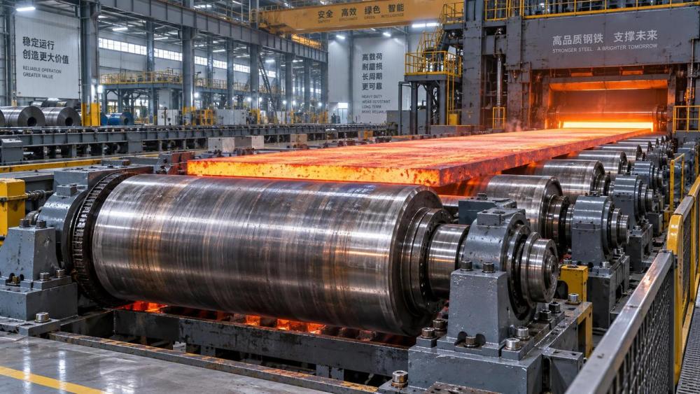
Alloy steel forged rollers deliver their longest service life where high contact stress is combined with repeated loading, impact, bending, abrasive contamination, or demanding thermal cycles. They are especially valuable when a roller is not merely guiding material but transmitting force, supporting heavy product weight, or maintaining dimensional stability through long operating periods. The benefit comes from forged grain flow, controlled heat treatment, tougher core properties, and better resistance to fatigue-related damage than many cast or lightly fabricated alternatives.
Heavy-load conditions that justify forged alloy steel construction
The strongest application case is not simply “high weight.” A roller may carry a large static load without needing a premium forged body if rotation is slow, impacts are limited, and replacement is easy. Forged alloy steel becomes more relevant when the load repeatedly changes direction, concentrates at a narrow contact line, or arrives with shock.
Typical high-value environments include:
- Steel mills and metal processing lines: pinch rollers, work rollers, support rollers, guide rollers, coiler components, and transfer-table rollers exposed to hot stock, scale, contact pressure, and cyclic torque.
- Mining and aggregate operations: crusher-feed rollers, high-load belt conveyor rollers, screening equipment rollers, feeder components, and material-handling rollers subjected to abrasive fines and impact from irregular rock.
- Bulk ports, ship loaders, and heavy conveyor systems: rollers supporting dense bulk material where belt tension, misalignment, contamination, and continuous operation can accelerate wear.
- Paper, board, and converting machinery: press rolls, calender-related support components, and tension rollers where deflection control and surface integrity affect product consistency.
- Heavy-duty presses and forming equipment: rollers that guide plate, coil, profiles, or formed sections while receiving intermittent but severe load peaks.
- Construction, recycling, and agricultural machinery: track rollers, support rollers, compacting rollers, and feed rollers where mud, debris, vibration, and shock loading act together.
In these environments, failure is rarely caused by one factor alone. A roller can be strong enough in basic compression but still crack at a shoulder, lose surface hardness, or develop permanent runout after many loading cycles. Material selection must therefore address surface wear, core toughness, fatigue strength, and geometry as one system.
Why forging changes service life under repeated stress
A forged roller begins as a worked steel billet or ingot that is shaped under compressive force. This process can refine the material structure and orient grain flow more favorably around the part profile. When properly specified and controlled, the resulting component generally has fewer internal discontinuities than a comparable component made by a process more prone to shrinkage cavities, porosity, or nonuniform structure.
That structural continuity matters most at fatigue-sensitive locations: the transition between roller body and journal, keyway or spline areas, bearing seats, grooves, and radiused shoulders. These areas experience stress concentration. A roller can appear sound after machining, yet a small internal defect or poorly supported geometric transition may become the starting point for a crack after repeated bending or torque reversal.
Alloy steel also allows engineers to tailor properties through composition and heat treatment. Chromium, molybdenum, nickel, manganese, and other alloying elements may be selected to improve hardenability, toughness, wear resistance, or resistance to tempering at elevated service temperature. The exact grade is not the decision by itself; the useful question is whether the chosen material and treatment produce the required hardness profile and core strength for the actual duty.
A high surface hardness can resist indentation and abrasive wear, but a roller hardened too deeply or too aggressively may lose the toughness needed to survive impact. Conversely, a roller with a tough but insufficiently hard surface may deform, score, or wear rapidly. Long-life forged rollers are usually designed around this balance rather than around the highest available hardness value.
Where cast, fabricated, or standard steel rollers may be insufficient
Not every roller needs a forged alloy steel body. Welded fabricated rollers can be practical for lower contact loads, large-diameter applications with modest duty, or equipment where shell replacement is expected. Cast rollers may also be appropriate where geometry, damping characteristics, or cost structure favors casting and service conditions are well controlled.
The risk grows when these alternatives are placed into severe cyclic duty without adequate design margin. A fabricated shell may be vulnerable at weld zones if bending, impact, or torque is high. A cast component may require careful evaluation of internal soundness and fatigue performance before it is used in a heavily loaded rotating position. Standard carbon steel can be adequate for shafts and rollers with low wear exposure, but may lack hardenability or toughness consistency in large cross-sections.
Read the operating scene before specifying the roller
A useful evaluation starts at the machine, not at the material certificate. Observe what the roller is actually doing during production. Is it carrying load continuously, receiving impact at intervals, squeezing material, pulling a belt, steering a product path, or rotating freely under contamination? The same outside diameter can serve very different mechanical functions.
Begin with the load path. Determine whether force is applied at the center of the roller, near one end, or across a moving contact band. Center loading mainly drives bending and deflection. Edge loading can overload bearings and create severe stress at one journal. Narrow line contact increases Hertzian contact stress and can produce surface cracking even where total machine load appears acceptable.
Next, separate nominal load from peak load. Equipment ratings often describe normal operation, while roller damage may occur during jams, uneven material entry, abrupt acceleration, impact loading, or a stalled conveyor. A roller designed only for steady-state values can be adequate on paper and still be unsuitable in service.
Rotation speed also changes the problem. At low speed, gross deformation and contamination may dominate. At higher speed, balance, runout, bearing fit, surface finish, and lubrication-related heating become more important. A forged roller cannot compensate for poor dynamic balance or a journal machined outside the bearing manufacturer’s fit requirements.
Material and heat-treatment choices should follow the failure mode
Selection should be driven by the damage the previous roller experienced. Calling for alloy steel forging without identifying the dominant failure mechanism can lead to unnecessary cost or a roller that fails in a different way.
When the surface wears before the body fails
Abrasive particles, hard scale, mineral fines, and rough product contact can remove material from the roller surface. Here, the working layer may need induction hardening, through-hardening, carburizing, nitriding, hardfacing, or a separate wear-resistant sleeve, depending on the application. The appropriate route depends on required depth, repair strategy, contact pressure, and whether the surface must later be reground.
Hardening treatment must account for the roller’s diameter. A treatment that produces suitable hardness on a small roller may give a shallow effective case or an undesirable hardness gradient on a much larger body. Ask for the required effective depth and hardness range at the actual working surface, not only a general statement that the roller is “heat treated.”
When cracks begin around journals or transitions
This pattern points toward fatigue, stress concentration, misalignment, or excessive bending. The roller should be reviewed for journal diameter, fillet radius, shoulder geometry, keyway placement, bearing span, and loading position. A stronger alloy grade may help, but geometry often has equal or greater influence. Sharp transitions and undersized journals can defeat otherwise good material quality.
Forged construction is especially useful in this situation because the roller body and journals can be produced as an integrated structure rather than assembled from sections. However, the forged blank still requires careful machining and inspection. Tool marks, grinding burns, and aggressive surface finishing near high-stress areas can reduce fatigue life.
When the roller bends or loses alignment
Permanent runout usually indicates insufficient section stiffness, overload, inadequate support spacing, or a shaft-body design that does not match the load path. Increasing hardness will not correct this. Review outer diameter, bore configuration, wall thickness where applicable, journal size, bearing centers, and allowable deflection. In long rollers, deflection may affect both roller life and product quality by creating uneven pressure or tracking errors.
Specifications that deserve more attention than a generic grade callout
A drawing that only states “forged alloy steel roller” leaves too much open. The component should be specified as a functional part, with material and manufacturing requirements connected to the duty.
- Roller body diameter, face length, journal dimensions, bore details, and keyway or spline geometry.
- Maximum operating load, expected shock load, torque, rotational speed, and duty cycle.
- Contact medium: steel strip, belt, bulk solids, wet material, coated product, or another roller.
- Required surface hardness, effective hardened depth, core-property expectations, and permitted grinding allowance.
- Surface finish and runout requirements for the roller face and bearing journals.
- Heat-treatment method, required post-treatment machining, and areas that must remain machinable.
- Inspection requirements such as dimensional verification, hardness testing, ultrasonic examination where appropriate, magnetic particle inspection of critical areas, and material traceability.
- Balance requirements where rotational speed and roller mass make imbalance consequential.
These details help distinguish a roller designed for real duty from one that is only similar in appearance. They also give the manufacturing team a clearer basis for forging allowance, machining sequence, heat-treatment planning, and final inspection.
Installation issues that can erase the advantage of a better roller
Even a well-made forged component can fail early when installation conditions are ignored. Bearings mounted with incorrect fits may creep, overheat, or damage the journal. Misaligned housings can impose bending that was never included in the design load. Over-tightened seals can generate heat and wear; ineffective seals allow abrasive contamination to reach bearing positions and roller surfaces.
Before commissioning, verify journal dimensions after final finishing, bearing seating condition, housing alignment, coupling alignment where driven, and roller runout at the working face. During early operation, look for unusual temperature rise, uneven contact marks, vibration, or localized polishing that indicates edge loading. These are not minor cosmetic observations; they often reveal the conditions that later cause fatigue damage.
Lubrication should also be evaluated as part of the assembly. The correct lubricant type, delivery interval, contamination protection, and purge practice depend on speed, load, environment, and bearing design. A roller surface may remain intact while bearing damage creates increasing runout and finally overloads the roller journals.
Making the replacement decision after a failure
When replacing a damaged roller, avoid treating the old part as the complete specification. Its failure can reveal that the original design was under-sized, improperly treated, or installed in a machine condition outside its intended limits. Preserve evidence before the part is discarded: note crack location, wear pattern, diameter loss, bearing condition, shaft runout, and whether damage is symmetrical across the face.
A crack at one shoulder suggests a different corrective path from uniform surface wear. Repeated damage on the same side of multiple rollers may indicate frame alignment or product tracking rather than a metallurgical defect. Deep scoring concentrated near the ends can point to contamination, belt mistracking, or edge contact. The most durable replacement is the one that addresses the physical source of damage, not merely the one with a higher-strength material description.
Alloy steel forged rollers are therefore most justified in equipment where downtime, access difficulty, high load cycling, or damage consequences make premature replacement unacceptable. Their value is strongest when forging quality, heat treatment, roller geometry, surface requirements, and installation control are specified together.
Related News
- How to Assess a Rigid Coupling Supplier for Bore Accuracy and Traceable QualityOct 08, 2026Tribology & Kinematics Expert
- Titanium Alloys Compared: Balancing Strength, Corrosion Resistance, and MachinabilityOct 08, 2026CNC Kinematics Architect
- Where Ductile Iron Dismantling Joints Reduce Alignment Risk in Water PipelinesOct 08, 2026Pipeline Metallurgy Scientist
- Selecting a Precision Bearing Sleeve: Fits, Runout, and Material ChoicesOct 08, 2026Tribology & Kinematics Expert
- Face Milling Cutters: How Insert Geometry Affects Finish on Steel and AluminumOct 08, 2026CNC Kinematics Architect
- Single-Acting Cylinders for Clamping: Stroke, Force, and Return Spring ConsiderationsOct 07, 2026Fluid Power Control Strategist