
Thrust Roller Bearings for Screw Jacks: Selection Factors Under High Axial Loads
Screw jacks convert rotary input into controlled linear motion, but the lifting screw, nut, gear train, and housing can perform as intended only when axial thrust is transferred through a suitable support arrangement. Under high axial loads, thrust roller bearings are often selected because line contact between rollers and raceways can carry substantially greater axial force than a comparably sized ball thrust bearing. Selection still depends on the entire load path. A bearing with adequate catalog capacity can fail early when the housing seat deflects, the screw is misaligned, lubricant is unsuitable, or shock loading has been omitted from the design calculation.
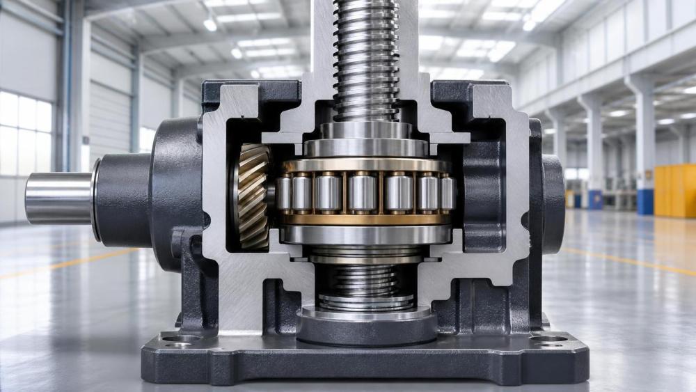
For a screw jack, the bearing normally sits at the point where the rotating screw or worm-driven lifting element reacts the load into the gearbox or jack housing. Its function is to limit axial movement while allowing rotation with controlled friction. The bearing arrangement must therefore be assessed together with screw diameter, thread type, gear ratio, housing rigidity, mounting orientation, duty cycle, travel limits, and the way the lifted structure distributes load.
Start With the Actual Axial Load Path
The nominal lifting force is only one input. The bearing may see a higher axial reaction because of mechanical losses, eccentric loading, acceleration, impact at seating, or force introduced when several jacks are linked by shafts and gearboxes. In a synchronized lifting arrangement, unequal elevation, frame flexibility, or variation in screw friction can shift load from one jack to another. A bearing selected only against the evenly divided static load can therefore be undersized in service.
Establish separate values for the sustained working load, peak operating load, occasional shock load, and any preload created during assembly. The direction of each load matters. A single-direction thrust roller bearing is generally appropriate where thrust remains consistently in one direction and a separate arrangement handles return force or reverse travel. Where a jack must carry material load in both directions, a double-direction thrust bearing or a paired arrangement may be necessary. Direction reversal should not be assumed to be harmless simply because the magnitude is low; the inactive raceway can experience skidding or loss of stable roller contact if the arrangement is poorly loaded.
Static capacity deserves particular attention in slow-moving screw jacks. Many applications operate at low rotational speed, with long dwell periods while the load remains supported. In this condition, permanent indentations in the raceways can be a greater concern than fatigue life. Such indentations may lead to uneven rotation, vibration, rising breakaway torque, and inaccurate positioning. Compare the highest possible transmitted thrust with the bearing's static load rating using the bearing manufacturer's stated method, including the applicable service factor for shock, vibration, and uncertain load distribution.
Choose the Bearing Type Around Space, Speed, and Misalignment
Cylindrical roller thrust bearings provide high axial capacity and are commonly suited to compact, rigid assemblies that can maintain close alignment. Their rollers run perpendicular to the shaft axis, producing low axial friction under suitable lubrication. They are generally intolerant of angular misalignment, however. If the housing bore, support washer, or mating shoulder is not square to the screw axis, roller loading becomes concentrated near an edge.
Spherical roller thrust bearings can accommodate a degree of misalignment and may carry combined axial and radial loading, depending on the specific design and operating conditions. Their ability to tolerate shaft or housing deflection can be valuable in large fabricated structures or installations where the mounting surface cannot be machined as a single rigid reference. This advantage does not eliminate the need for alignment control. Excessive tilt still reduces contact quality, affects heat generation, and can shorten service life.
Tapered roller bearing arrangements may also be used where axial and radial reactions must be controlled together, particularly when the jack shaft or worm arrangement produces meaningful radial force. They normally require careful adjustment of endplay or preload and must be evaluated as a matched system rather than as a direct substitute for a dedicated thrust roller bearing. A design that uses tapered rollers solely to solve an assembly-tolerance problem may add adjustment sensitivity and maintenance exposure without addressing the root cause.
Thrust needle roller assemblies can fit very limited axial envelopes, but their compactness should be weighed against load capacity, washer hardness requirements, and sensitivity to raceway condition. They often rely on hardened, ground mating washers or directly prepared shaft and housing surfaces. A rough, soft, or improperly hardened contact face can quickly become the limiting element, regardless of the needle roller cage rating.
Catalog Ratings Need the Correct Operating Context
Dynamic load rating is used to estimate rolling fatigue life under rotation. A screw jack that rotates slowly for only short intervals may accumulate relatively few bearing revolutions, yet this does not automatically justify a smaller bearing. Dwell load, corrosion risk, lubricant separation, vibration, and false brinelling during transport or standby can dominate the failure mechanism. Conversely, a continuously cycling jack may generate enough revolutions for conventional fatigue-life calculations to become central.
Calculate bearing speed from screw rotational speed rather than linear lifting speed alone. Screw lead establishes the relationship: a high-lead screw travels farther per revolution, while a fine lead requires more revolutions for the same stroke. Gear reduction between the drive motor and screw must also be included. This speed affects lubricant selection, churning losses, heat removal, and the minimum load needed to maintain rolling stability in some bearing types.
Temperature should be treated as an operating variable, not a nameplate afterthought. Internal heating can arise from lubricant shear, seal friction, preload, high oil level, or misalignment. Ambient conditions may be much lower or higher than the temperature at the bearing. Where the jack is installed near furnaces, outdoor thermal cycling, washdown areas, or hydraulic equipment, verify the permissible temperature range for the bearing steel, cage, seals, grease, and adjacent polymer components. Thermal expansion can also alter internal clearance and tighten a bearing arrangement that was acceptable during room-temperature assembly.
Mounting Surfaces Are Part of the Bearing System
A thrust roller bearing needs flat, sufficiently rigid, and correctly supported raceways. The screw shoulder, support washer, cover plate, or housing seat must carry the bearing load without local yielding or distortion. Contact faces should meet the required hardness, surface finish, and geometric tolerances stated for the selected bearing. In many designs, the housing cover is not merely a retaining component; it is a loaded structural member. Its thickness, bolt pattern, material, and contact area should be checked against bending under peak thrust.
Perpendicularity between the shaft axis and the support face is especially important. A small angular error can cause non-uniform roller contact. The resulting edge stress may appear as localized discoloration, scoring, spalling, or uneven raceway marks during inspection. Machining the bearing seat and its locating bore in one controlled setup can reduce stack-up error. Where fabrication requires separate components, the assembled geometry should be verified rather than inferred from individual part dimensions.
Axial location must prevent race rotation relative to the shaft or housing when creep is possible. Under cyclic thrust, micro-movement between a washer and its seat can fret the contact surfaces and release abrasive debris into the lubricant. A proper shoulder, interference condition where applicable, clamping force, or locating feature should be selected according to the bearing design. Fasteners that clamp a support washer or cover require controlled tightening. Uneven bolt load can distort a thin cover and introduce bearing misalignment.
Lubrication Must Match Duty and Orientation
Grease is common in enclosed, intermittent-duty screw jacks because it remains near the bearing and simplifies sealing. The grease must provide adequate base-oil viscosity at operating temperature, resist mechanical working, and remain compatible with seal materials and any lubricant used on the screw and gears. Overpacking is a frequent error. Excess grease can churn, raise temperature, and force lubricant past seals. Insufficient grease can leave roller contacts starved, particularly in vertically mounted units where gravity and repeated motion redistribute lubricant.
Oil lubrication may be preferable in higher-speed or continuous-duty jacks, especially when the gear train already uses an oil bath or circulation system. The oil level must be validated at the bearing location and in the actual mounting orientation. A bearing above the nominal oil level may require splash delivery, a passage, wick, or directed feed. A bearing submerged too deeply can produce drag and heat. Lubricant channels should avoid dead ends where contamination, degraded oil, or assembly debris can accumulate.
Contamination control is closely tied to bearing life. Fine metallic particles from gears, screw wear, or machining residue can damage raceways. Water ingress can cause corrosion and reduce lubricant film strength. In outdoor or washdown service, sealing should be considered alongside breather design, pressure changes, and drain paths. A seal that excludes water but traps pressure inside the housing can create leakage elsewhere. During assembly, clean tools, protected parts, and filtered lubricant are more effective than trying to compensate later with frequent relubrication.
Alignment Cannot Be Delegated to the Bearing
A screw jack may be structurally aligned at no load and still operate out of alignment once the lifted equipment is engaged. Guide rails, trunnions, couplings, connecting shafts, and the supported frame all influence the screw axis. Side loading on the lifting screw can create bending that transfers into the thrust bearing arrangement. This is particularly relevant in multi-jack systems, where a rigidly linked drive can force one unit to follow the position error of another.
Commissioning should include observation through the full travel range and at representative load. Rising drive torque, inconsistent travel rate, unusual temperature increase, or repeatable position deviation can indicate misalignment or uneven load sharing. These symptoms should be investigated before changing bearing type or increasing motor size. A larger bearing may withstand the condition longer, but it will not correct a bent load path or an unstable mounting frame.
Couplings deserve the same scrutiny. A flexible coupling can accommodate limited angular or parallel offset, but it does not remove the radial forces created by a badly positioned drive shaft. Universal joints, long connecting shafts, and intermediate supports may introduce cyclic torque variation. Their arrangement should be reviewed together with the jack input shaft and bearing support geometry.
Material, Heat Treatment, and Inspection Evidence
High axial load capacity depends on raceway hardness, rolling-contact quality, dimensional consistency, and clean steel or other specified material quality. The bearing itself should be traceable to its part designation, manufacturing lot where available, and stated performance data. For critical lifting equipment, documentation requirements may include material certificates, dimensional records, hardness evidence, or non-destructive examination of related forged shafts and machined housings. The exact scope should be defined in the technical specification rather than requested only after components arrive.
Machined mating components require equivalent discipline. A hardened bearing washer cannot compensate for a housing seat with excessive runout, poor flatness, embedded scale, or damaged threads that prevent even clamping. Inspection plans should identify which surfaces establish bearing alignment, how they will be measured, and when measurements occur. Measuring a cover plate before coating, then assembling it over uneven paint buildup or weld spatter, can invalidate otherwise acceptable machining results.
Corrosion protection should be kept away from precision bearing contact surfaces unless the bearing design expressly permits it. Paint, zinc-rich coating, or heavy preservative trapped beneath a support washer can change seating geometry. Bare machined surfaces should instead receive a compatible temporary corrosion inhibitor before shipping and be cleaned only as specified during assembly.
Specification Details That Prevent Late Rework
A usable purchase specification identifies the thrust load direction, maximum working and peak loads, required travel cycles, screw speed, mounting orientation, target service temperature, lubrication method, environmental exposure, and available axial space. It should also state whether the bearing must accommodate radial load or misalignment, whether a washer is included, and which components form the mating raceways. Calling for a “high-load thrust bearing” without these details leaves critical assumptions unresolved.
- Define the completed assembly drawing, including shoulder dimensions, housing-seat geometry, cover thickness, and fastener arrangement around the bearing.
- State the required internal clearance, endplay, or preload condition when the selected arrangement needs adjustment.
- Require preservation and packaging that protect raceways from impact, moisture, and vibration during transport; heavy thrust bearings can be damaged before installation if they are allowed to shift within a crate.
- Record the approved lubricant, fill quantity or oil-level reference, and any initial relubrication interval needed before commissioning.
Receiving inspection should confirm part identification, visible corrosion, packaging integrity, and freedom of impact damage before the bearing is placed in stock or assembled. Bearings should remain in their protective packaging until the work area and mating components are ready. Handling through the rollers, dropping a washer onto a hard surface, or using an impact tool to seat a component can introduce damage that may not be obvious at startup.
During installation, force should be applied only through the ring or washer being fitted. Never transmit mounting force through rollers from one raceway to another. Rotate the assembly by hand where practical after tightening, while recognizing that a heavily loaded thrust arrangement may not turn freely without its intended lubricant and operating load. The final acceptance record should include measured axial position, tightening values where applicable, lubricant confirmation, and the initial no-load and loaded operating observations.
Thrust roller bearings for screw jacks perform reliably when the bearing, screw, housing, lubrication, and structure are treated as one mechanical system. Capacity rating remains necessary, but stable service depends equally on the quality of the supporting surfaces, realistic load assumptions, controlled assembly, and evidence that alignment remains acceptable after the equipment reaches its working condition.
Related News
- How to Assess a Rigid Coupling Supplier for Bore Accuracy and Traceable QualityOct 08, 2026Tribology & Kinematics Expert
- Titanium Alloys Compared: Balancing Strength, Corrosion Resistance, and MachinabilityOct 08, 2026CNC Kinematics Architect
- Where Ductile Iron Dismantling Joints Reduce Alignment Risk in Water PipelinesOct 08, 2026Pipeline Metallurgy Scientist
- Selecting a Precision Bearing Sleeve: Fits, Runout, and Material ChoicesOct 08, 2026Tribology & Kinematics Expert
- Face Milling Cutters: How Insert Geometry Affects Finish on Steel and AluminumOct 08, 2026CNC Kinematics Architect
- Single-Acting Cylinders for Clamping: Stroke, Force, and Return Spring ConsiderationsOct 07, 2026Fluid Power Control Strategist