
Spindle Bearing Selection for CNC Machines: Speed, Preload, and Runout
The bearing set is the spindle’s final geometric reference. Motor power, toolholder quality, and control resolution cannot compensate for a spindle that loses stiffness under cutting load, generates excessive heat at speed, or carries unacceptable runout into the tool taper. Selection therefore begins with the required cutting process rather than with a bearing catalogue: a 30,000 rpm aluminum-finishing spindle, a high-torque mold-milling spindle, and a grinding spindle may all use angular-contact bearings, yet require materially different contact angles, preload levels, lubrication arrangements, and accuracy classes.
For machine tool bearings for CNC spindles, the central trade-off is straightforward but demanding to manage: increasing preload improves rigidity and positional stability, while also increasing friction, heat generation, and the risk of reducing allowable speed and fatigue life. Runout is not an isolated bearing specification either. It is the accumulated result of bearing accuracy, spindle shaft and housing geometry, fits, assembly cleanliness, preload consistency, thermal displacement, and the condition of the taper or tool interface.
Start with the spindle duty cycle, not the nominal maximum speed
A spindle may be rated for a high maximum rotational speed but spend most of its operating time at a lower range under intermittent or continuous load. Bearing selection should reflect the actual speed-load spectrum, acceleration frequency, tool diameter, cutting forces, expected thermal duty, and whether the spindle is belt-driven, motorized, or gear-assisted.
The conventional speed parameter is the nDm value, calculated as rotational speed in rpm multiplied by bearing mean diameter in millimetres. It is useful for comparing operating severity, but it is not a stand-alone approval criterion. The permissible speed supplied by a bearing manufacturer depends on preload, lubricant type and quantity, cage design, bearing orientation, cooling, sealing, and the ability of the spindle assembly to remove heat. A bearing operating at the same nDm value can behave very differently under oil-air lubrication and under grease lubrication.
For this reason, a catalogue limiting speed should be treated as a boundary established under defined conditions, not as a target operating point. A spindle intended to remain close to that limit needs a complete thermal and lubrication assessment. Selecting a bearing simply because its listed limiting speed exceeds the required spindle speed leaves little margin for preload variation, lubricant churning, ambient temperature, contamination, or reduced cooling performance.
High-speed milling often rewards a spindle arrangement with low-friction preload, optimized ceramic rolling elements, controlled grease quantity or oil-air lubrication, and effective housing cooling. Heavy roughing, interrupted cutting, large-diameter tools, and deep-pocket machining place more value on bending stiffness and axial load capacity. In these cases, accepting a lower top speed can be the correct engineering decision.
Why angular-contact ball bearings dominate precision spindle arrangements
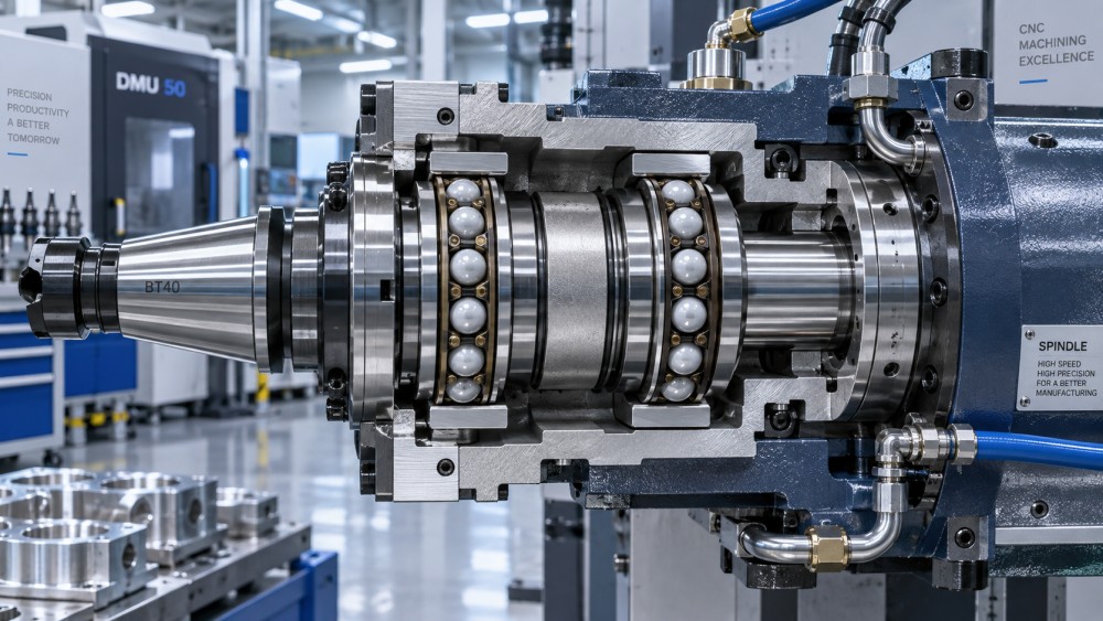
Precision angular-contact ball bearings are the most common rolling bearings in high-speed CNC spindles because they can carry combined radial and axial loads while providing controlled axial stiffness. They are normally mounted in matched sets so that axial forces can be supported in both directions and preload can be established predictably.
Contact angle is one of the first variables to examine. A smaller contact angle generally favors higher speed because it reduces axial force components and frictional effects. A larger contact angle improves axial stiffness and axial load capability, but raises the thermal and speed penalty. The appropriate angle therefore follows the process load direction:
- High-speed finishing spindles benefit from arrangements optimized for rotational speed and moderate cutting loads.
- General-purpose milling spindles need a balanced response to radial cutting force, axial plunge loads, and changing tool lengths.
- Drilling, tapping, and operations with significant thrust require careful attention to axial stiffness and bidirectional thrust capacity.
- Grinding spindles frequently prioritize low vibration, low heat generation, and stable rotational accuracy over high static load capacity.
Duplex sets may be arranged back-to-back (DB), face-to-face (DF), or in tandem (DT). A back-to-back arrangement provides a wide effective support span and strong resistance to overturning moments, making it common at the tool end of milling spindles. Face-to-face arrangements are more tolerant of angular misalignment but offer lower moment stiffness. Tandem pairs increase axial load capacity in one direction and must be combined with another bearing or set to accommodate reverse thrust.
The rear bearing set is not merely a secondary support. Its configuration determines how thermal growth is absorbed, how axial location is controlled, and whether preload remains stable as the shaft temperature changes. A fixed-locating arrangement at one end with an accommodating arrangement at the other is often required in longer spindles, but the details depend on shaft material, housing design, bearing type, and the selected preload method.
Hybrid bearings, typically using ceramic balls with steel rings, can offer lower centrifugal force, reduced friction, and better resistance to smearing under appropriate operating conditions. Those characteristics make them useful in demanding high-speed spindles. They do not eliminate the need for correct lubrication, accurate fits, or clean assembly. Hybrid construction is not a universal correction for an unsuitable preload or poor thermal design.
Preload is a stiffness setting with thermal consequences
Preload removes internal clearance and creates a defined elastic force within the bearing set. In a spindle, this produces immediate benefits: higher axial and radial stiffness, improved resistance to ball skidding under light load, better control of tool-point displacement, and more consistent rotational behaviour during direction changes.
Those benefits are accompanied by frictional torque. Friction raises bearing temperature; temperature changes ring dimensions and shaft-to-housing fit conditions; those changes can increase preload further. If the design cannot stabilize this feedback loop, thermal runaway becomes possible. The risk is greatest where high preload, high speed, heavy grease fill, restricted heat dissipation, and tight interference fits occur together.
Preload terminology must be read carefully. Terms such as light, medium, and heavy preload are manufacturer-specific matched-set classifications, not universal force values that can be substituted across brands or bearing series. The actual preload force also varies with bearing size, contact angle, geometry, and mounting condition. Evaluation documents should therefore specify the bearing series, matched-set designation, arrangement, intended operating speed range, lubrication method, and preload control method rather than relying on a generic preload description.
There are two main ways to establish preload. Rigid preload uses spacers or a controlled axial clamping position to impose a fixed displacement. It offers high stiffness but can be sensitive to differential thermal expansion. Spring preload applies a more nearly constant axial force over a range of displacement and can better accommodate thermal movement, although it provides lower stiffness than a comparable rigidly preloaded arrangement. The choice is a system-level decision, not a bearing-only decision.
Preload should also be reviewed against the real machining load. Under-cutting preload reduces stiffness and can allow undesirable ball motion, loss of contact control, and lower surface quality. Over-preloading may produce good static displacement figures during inspection but poor high-speed stability after thermal equilibrium is reached. A spindle is not properly assessed until its temperature, vibration, power draw, and runout are examined at operating speed and after a representative warm-up cycle.
Runout must be traced through the entire tolerance chain
Spindle runout is often described as a single value measured at the taper, a test arbor, or a tool gauge line. That number is important, but it does not identify the source of the error. The observed tool-point runout is a stack-up of several contributors:
- radial runout and raceway geometry of the bearings;
- shaft journal roundness, cylindricity, shoulder squareness, and surface finish;
- housing bore geometry and the alignment of front and rear bearing seats;
- fit-induced distortion of bearing rings;
- spacer parallelism and axial face quality in rigidly preloaded sets;
- taper cleanliness, taper wear, drawbar force, toolholder condition, and balance;
- thermal growth and dynamic deflection under speed and cutting force.
A high-accuracy bearing cannot preserve its catalogue-level geometry if it is mounted on a lobed journal, pressed against an out-of-square shoulder, or distorted by an unsuitable interference fit. Equally, a low measured runout at rest does not prove adequate rotational accuracy during machining. Centrifugal effects, imbalance, thermal gradients, and preload drift can alter the result substantially at speed.
It is useful to distinguish between bearing rotational accuracy, spindle nose runout, toolholder runout, and tool-point runout. The first is a bearing characteristic measured under controlled conditions. The second reflects spindle assembly quality. The third introduces the taper and holder interface. The fourth includes tool geometry and overhang, where small angular errors become larger radial displacement at the cutting edge. A tolerance requirement should state the measurement location, indicator method, reference artifact, rotational condition, and whether the result is total indicator reading or another defined metric.
Accuracy classes also require disciplined interpretation. ISO 492 defines dimensional and running-accuracy tolerances for radial bearings, while regional and manufacturer designations may use different class names. ABEC classifications are widely referenced in the market, but an ABEC number alone does not define preload, cage design, lubrication performance, vibration level, noise, material condition, or suitability for a high-speed machine-tool spindle. Cross-reference claims should be verified against the complete manufacturer specification rather than assumed from a nominal class label.
Fits, seating geometry, and assembly can invalidate a sound bearing choice
Because the inner ring rotates with the spindle shaft in most designs, the shaft fit must prevent creeping under load and speed. Yet excessive interference expands the inner ring, reduces internal clearance or changes the intended preload, and can distort raceway geometry. The housing fit has the opposite thermal problem: the outer ring is constrained by a housing that may heat and expand at a different rate from the shaft. Aluminium housings, steel housings, and cooled cartridges do not behave identically.
Fit selection must therefore consider ring rotation, load direction, ring wall thickness, material combinations, operating temperature, and assembly method. Generic fit tables are useful starting points but should not replace a review of the specific spindle stack-up. The effect of fits is particularly significant with thin-section or small-bore precision bearings, where ring deformation may consume a meaningful portion of the intended preload window.
Shoulders and spacers need sufficient rigidity and accurate perpendicularity to prevent the rings from being clamped unevenly. Mounting force must be applied to the ring receiving the interference fit; transmitting press force through rolling elements can damage raceways before the spindle has entered service. Cleanliness is equally fundamental. A small hard contaminant in a precision bearing can introduce local indentation, vibration, noise, and a permanent degradation of rotational accuracy.
Grease selection and fill quantity should be treated as engineered parameters. Excess grease is a frequent cause of rapid temperature rise during spindle run-in. Grease lubrication may be practical and reliable within its intended speed range, but high-speed duty can require metered oil-air or oil-mist systems designed to deliver lubricant without creating excessive churning losses. Lubrication system capability, not bearing speed rating alone, determines whether the intended operating point is sustainable.
Assess the bearing arrangement as a validated spindle system
A technically credible evaluation package links bearing selection to measurable spindle outcomes. It should identify the bearing arrangement and orientation, preload designation and method, contact angle, ball material, cage type where relevant, lubricant and delivery method, shaft and housing fit requirements, cooling arrangement, and permissible operating envelope. It should also define the acceptance measurements used after assembly.
Useful validation includes controlled run-in, temperature stabilization at representative speeds, vibration monitoring, rotational power or current trend observation, and runout measurement at the actual functional interface. Where the spindle will perform high-accuracy contouring or finishing, radial and axial displacement under representative load are more meaningful than a no-load runout result alone. For high-speed applications, balance quality of the complete rotating assembly—shaft, rotor, tool interface, retention system, and holder—must be considered alongside bearing accuracy.
The most costly selection error is treating speed, preload, and runout as independent catalogue filters. They are coupled variables. A higher-speed bearing arrangement may need lower preload and a more capable lubrication system; that may reduce static stiffness unless geometry or bearing spacing compensates. A high-stiffness arrangement may demand stronger thermal control and tighter assembly tolerances. Low runout requires not only precision bearings but also a tolerance chain capable of preserving their accuracy.
The correct bearing set is therefore the one that maintains required tool-point stability, temperature control, and rotational accuracy throughout the intended duty cycle—not the one with the highest speed number, the heaviest preload label, or the smallest isolated bearing runout value.
Related News
- Using Industrial Air Blow Guns to Clear Chips Without Spreading DebrisOct 15, 2026Fluid Power Control Strategist
- Ductile Iron Pipe Valves: Which AWWA Standards Apply to Water Main Projects?Oct 15, 2026Dr. Elias Vance
- Why Vacuum Suction Cups Lose Grip on MDF in Woodworking MachinesOct 15, 2026CNC Kinematics Architect
- Choosing a Variable Displacement Piston Pump Manufacturer: What to VerifyOct 15, 2026Fluid Power Control Strategist
- Parallel vs. Angular Pneumatic Grippers for Confined Assembly StationsOct 15, 2026Fluid Power Control Strategist
- Die Castings vs. Investment Castings: Which Costs Less at Your Production Volume?Oct 14, 2026Foundry Phase-Change Fellow