
Selecting Needle Roller Thrust Bearings for High Axial Loads and Limited Space
Selecting Needle Roller Thrust Bearings for High Axial Loads and Limited Space
Selecting a needle roller thrust bearing for high axial loads in a restricted installation envelope is not simply a matter of finding a bearing with the right bore, outside diameter, and thickness. These compact assemblies can carry substantial thrust loads relative to their axial height, but their performance depends heavily on the quality of the surrounding design. Raceway hardness, shaft and housing geometry, lubricant supply, mounting accuracy, speed, and load direction all affect whether the bearing delivers reliable motion or develops early scoring, overheating, and roller damage.
This matters in gearboxes, hydraulic pumps, machine tools, industrial presses, compact actuators, transfer equipment, construction machinery, and other power-transmission systems where axial space is scarce but the thrust load is real. In many of these assemblies, the bearing itself is inexpensive compared with the shaft, gearbox, pump housing, or downtime associated with a failure. The selection process therefore needs to evaluate the entire bearing arrangement rather than the catalog component in isolation.
A needle roller thrust bearing is especially attractive when a design needs a low-profile axial bearing with high load-carrying capability. Yet compactness has a trade-off: there is less tolerance for deflection, contamination, poor lubrication, or improvised raceway surfaces. The right decision begins with understanding what this bearing type is designed to do—and what it should not be expected to absorb.
Why the Bearing Arrangement Matters More Than the Cage
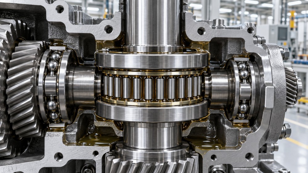
A typical needle roller thrust bearing consists of a cage holding closely spaced needle rollers. Depending on the design, it may be supplied as a roller-and-cage assembly alone or combined with hardened thrust washers. The rollers transmit axial force between two raceways while the cage keeps them evenly distributed. Because the rollers are slender and numerous, the arrangement uses radial space efficiently and keeps the axial section very thin.
The important distinction is that a needle roller thrust bearing primarily carries axial load. It is not a substitute for a radial bearing, nor should it be asked to compensate for meaningful shaft misalignment, bending, or housing distortion. A shaft commonly needs a separate radial-support arrangement—such as a cylindrical roller, deep-groove ball, tapered roller, or other suitable bearing—to control radial movement and maintain the thrust bearing’s contact geometry.
When an evaluator sees a compact thrust bearing in a drawing, the first question should be: what keeps the two thrust faces parallel under operating load? If the answer is uncertain, the nominal dynamic or static load rating alone will not make the design safe. Uneven contact can overload only part of the roller set, raise local contact stress, and initiate surface distress well before the calculated rating would suggest a problem.
Start with the Actual Axial Load, Not the Simplified Load Case
The load used for bearing selection should reflect the force seen during normal operation, start-up, stopping, reversal, overload events, and any hydraulic or mechanical transients relevant to the machine. In a gearbox, axial force may come from helical gears, worm gearing, preload systems, or thermal expansion. In a hydraulic assembly, pressure changes and cylinder motion can create fluctuating thrust. A screw drive or clutch mechanism may create short-duration but severe peak loads.
Static load capacity deserves particular attention where the bearing moves slowly, oscillates through small angles, or spends long periods under load. In these conditions, permanent indentation and false brinelling can become more relevant than conventional fatigue life. A bearing that appears adequately rated for continuous rotation may still be unsuitable if it experiences repeated vibration at standstill, shock loading, or a narrow oscillation range that prevents lubricant replenishment across the raceway.
Load direction is equally practical. Many needle roller thrust bearing configurations are intended for thrust in one direction only. If the shaft must carry axial force in both directions, the design may require two opposing thrust bearing assemblies, a different bearing family, or a location arrangement that controls reversal without unintentionally unloading one raceway. Do not assume that a pair of washers automatically creates bidirectional capacity; the complete assembly layout must be checked.
Questions worth resolving before comparing part numbers
- What is the maximum sustained axial load, and what short-term peak or shock load can occur?
- Is the load unidirectional, reversing, or intermittently applied?
- Will the bearing rotate continuously, index, oscillate, or remain stationary under vibration?
- What radial bearing system keeps the shaft centered and limits angular displacement?
- Can temperature changes alter preload, clearances, or thrust position during service?
These questions often expose a specification gap. A bearing request may list dimensions and a desired load rating but omit duty cycle, reversal frequency, or the peak load generated by an emergency stop. Those omissions should be addressed before supplier comparison, because the lowest-profile solution may not remain the lowest-risk solution after the full duty condition is considered.
Raceways Are a Design Requirement, Not an Installation Detail
Needle rollers need hard, smooth, dimensionally stable tracks. If thrust washers are supplied, they provide dedicated raceways and simplify the interface with the shaft shoulder and housing face. If the design uses the shaft or housing directly as a raceway, those surfaces must be engineered accordingly. A standard machined face, even if it looks smooth, may not have the hardness, flatness, surface finish, or wear resistance needed for concentrated rolling contact.
Using hardened washers is often the more robust choice when the shaft and housing material cannot be reliably heat treated or when service replacement is likely. It also separates bearing performance from variation in a casting, forged component, or machined housing. Direct raceway designs can save thickness and parts count, but they place greater demands on material selection, heat treatment control, grinding quality, and inspection. That is a reasonable trade only when those capabilities are clear in the manufacturing plan.
Housing rigidity deserves the same scrutiny. A thin flange, an unsupported cover plate, or a distorted casting can tilt the thrust surface under load. The bearing may then leave a recognizable contact pattern: wear concentrated on one side of the washers, localized roller marking, or edge damage. Increasing bearing size may not correct this. In many cases, the effective solution is a stiffer support face, a revised load path, or better control of shaft deflection.
Limited Space Does Not Eliminate the Need for Alignment
A thin thrust bearing is often selected precisely because there is no room for a larger angular-contact or tapered-roller arrangement. That packaging advantage should not lead to relaxed tolerance control. The mounting faces must be sufficiently perpendicular to the shaft axis, and the bearing must be seated without burrs, trapped debris, or cocking. A small assembly error can be significant when the bearing has minimal axial height and highly loaded rolling elements.
Shaft shoulders and housing abutments should provide full, stable support without interfering with the cage or roller path. Chamfers, fillet radii, and relief grooves need review against the washer geometry. A shoulder that contacts only part of the washer may create distortion; a radius that is too large can prevent the washer from seating. Installation drawings should show these interfaces explicitly rather than leaving them to shop interpretation.
Where machine tolerances or structural deflection make angular misalignment unavoidable, a needle roller thrust bearing may be the wrong primary solution unless another feature compensates for the condition. Spherical seating elements, different bearing arrangements, or redesigned supports may be more appropriate. Trying to force a rigid thrust bearing into a misalignment-prone system generally transfers the problem into the bearing raceway.
Lubrication, Speed, and Contamination Change the Decision
Needle roller thrust bearings operate with rolling contact, but they still depend on a stable lubricant film to limit friction and surface damage. Grease can be suitable in enclosed, moderate-speed mechanisms where relubrication access and grease compatibility are understood. Oil lubrication is frequently more suitable for higher speeds, elevated temperatures, or shared gearbox environments because it can remove heat and continuously renew the lubricant at the contact zone.
The lubricant choice cannot be separated from the surrounding system. Gear oils may contain additive packages that need to be assessed for bearing compatibility. Hydraulic oil may offer clean circulation but may not provide the same viscosity margin as a dedicated gear lubricant at operating temperature. In either case, the actual viscosity at bearing temperature is more useful than a room-temperature oil grade alone.
Contamination is particularly damaging in compact rolling contacts. Hard particles can dent raceways, while moisture and corrosive media can attack surfaces during shutdown periods. In pumps, mobile equipment, processing lines, and exposed industrial drives, sealing and cleanliness should be reviewed as part of bearing selection. It is not enough to specify a high-quality bearing if installation practices leave grinding debris in the housing or if the lubricant path bypasses available filtration.
Speed also affects cage behavior, heat generation, and lubricant distribution. Catalog limiting speeds are useful boundaries, but they do not fully represent a loaded system with marginal lubrication, thermal soak, or shaft runout. For demanding applications, confirm the supplier’s speed guidance for the actual bearing arrangement, lubricant method, load, and operating temperature rather than relying on a generic maximum value.
Comparing Common Arrangement Choices
The table is not a substitute for bearing-life calculation or supplier validation, but it helps separate a packaging decision from a reliability decision. Two arrangements can occupy nearly the same space while having very different requirements for machining control and field serviceability.
What to Request During Technical Evaluation
A meaningful technical submittal should go beyond an item description. Request the bearing designation, dimensional drawing, dynamic and static load ratings, speed guidance, recommended washer arrangement, material and heat-treatment information where relevant, lubrication guidance, and mounting recommendations. For an engineered assembly, include the shaft and housing drawings, expected load spectrum, operating temperature range, lubricant type, contamination exposure, and the method used to support radial load.
For OEMs and project teams buying through multiple supply channels, traceability and production consistency also matter. The bearing may be a standard catalog item, but washers, spacer rings, shafts, and housings may be custom-machined or sourced from different facilities. Their dimensions and surface conditions must work together. Material certificates, inspection records, and agreed acceptance criteria become more important when failure could affect a high-value gearbox, a fluid-power unit, or a difficult-to-access machine location.
This broader view is central to the way Global Industrial Machining & Piping Equipment Network (IMPE) approaches power-transmission information. Bearings are not treated as isolated commodities. Their service life is connected to shaft machining, forged or cast housing rigidity, lubricant control, sealing, gearbox layout, inspection capability, and the practical realities of installation and maintenance.
A Practical Final Check Before Release
Before releasing a design or purchase specification, review the assembly in its operating position rather than as separate parts on a bill of materials. Confirm that the axial load path is clear, the raceways are suitable, radial support controls shaft motion, and the lubricant reaches both rolling interfaces. Then consider the failure mode that would be hardest to diagnose after installation: a deflecting cover, a contaminated oil circuit, a direct raceway that was not adequately hardened, or a bidirectional load imposed on a one-direction arrangement.
A well-selected needle roller thrust bearing can provide a compact and durable answer to high axial load requirements. The reliable choice is rarely the thinnest assembly on paper. It is the arrangement whose load rating, raceway condition, alignment control, lubrication method, and manufacturing tolerances remain appropriate when the real machine begins to work.
Related News
- How to Assess a Rigid Coupling Supplier for Bore Accuracy and Traceable QualityOct 08, 2026Tribology & Kinematics Expert
- Titanium Alloys Compared: Balancing Strength, Corrosion Resistance, and MachinabilityOct 08, 2026CNC Kinematics Architect
- Where Ductile Iron Dismantling Joints Reduce Alignment Risk in Water PipelinesOct 08, 2026Pipeline Metallurgy Scientist
- Selecting a Precision Bearing Sleeve: Fits, Runout, and Material ChoicesOct 08, 2026Tribology & Kinematics Expert
- Face Milling Cutters: How Insert Geometry Affects Finish on Steel and AluminumOct 08, 2026CNC Kinematics Architect
- Single-Acting Cylinders for Clamping: Stroke, Force, and Return Spring ConsiderationsOct 07, 2026Fluid Power Control Strategist