
Selecting Drawn Cup Needle Roller Bearings for Compact High-Radial-Load Housings
Selecting Drawn Cup Needle Roller Bearings for Compact High-Radial-Load Housings
Drawn cup needle roller bearings are often chosen when a machine needs meaningful radial load capacity but cannot afford a large bearing envelope. They appear in compact gearboxes, pumps, planetary drives, conveyor rollers, agricultural equipment, actuator mechanisms, machine-tool assemblies, and many fabricated or cast housings where every millimeter matters.
The selection can look deceptively simple: choose the shaft diameter, confirm the outside diameter fits the bore, and compare catalog load ratings. In practice, that approach misses the reasons these bearings usually fail early. A drawn cup bearing uses a thin, hardened outer ring formed from sheet steel. The housing is therefore not just a surrounding component; it becomes part of the bearing system. Bore geometry, housing stiffness, shaft raceway quality, lubricant condition, and installation force can all change the result.
For technical evaluators, the most useful question is not “Which bearing fits?” but “Can the housing, shaft, assembly process, and operating environment support this bearing design?” That distinction matters especially in high-radial-load applications, where compactness is valuable but tolerance for error is limited.
Why the Housing Deserves Early Attention
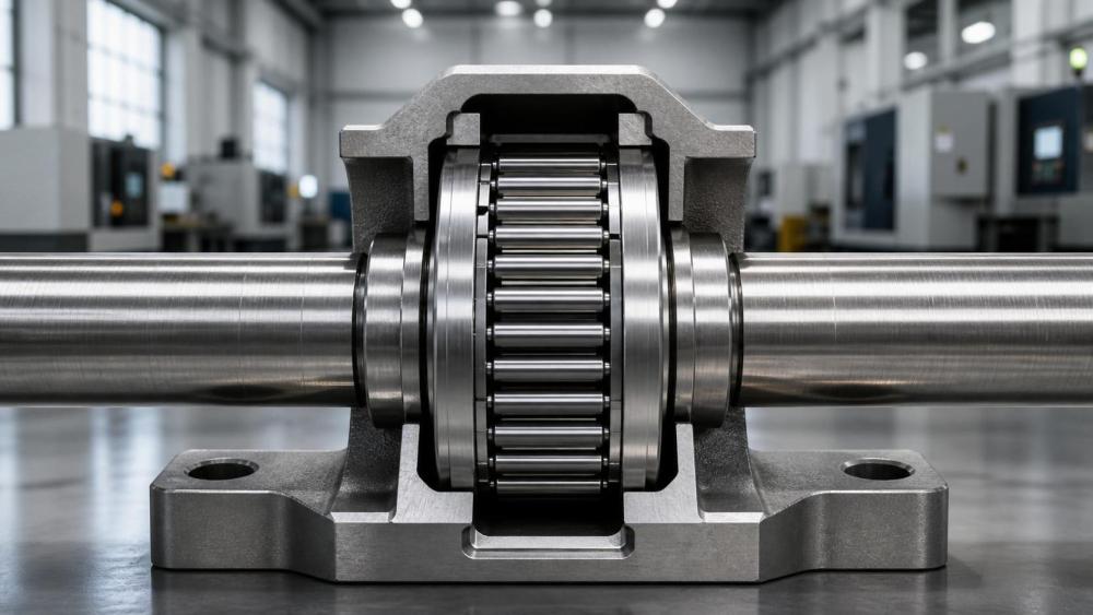
Unlike a conventional bearing with a comparatively rigid machined outer ring, a drawn cup needle roller bearing relies on an interference fit in the housing bore for retention and support. Once installed, the thin cup follows the shape of that bore more readily than a heavier bearing ring would. If the bore is tapered, out of round, interrupted by a casting defect, or distorted by a thin housing wall, the rollers may no longer see a uniform load path.
This is a recurring issue in compact cast housings and welded fabrications. A design may have adequate nominal bore diameter, yet insufficient local wall thickness around the bearing seat. Under external loading, bolting forces, or thermal movement, the seat can deform. The bearing then carries load over a reduced contact zone, increasing edge stress and accelerating wear. The damage may show up as noise, rough rotation, discoloration, or spalling on the shaft raceway before the bearing itself is visibly collapsed.
Housing material also affects the decision. Steel housings generally provide stable support, while aluminum, some light alloys, and lower-stiffness cast structures need closer review of fit retention and deformation. A softer housing is not automatically unsuitable, but the interference fit, operating temperature range, wall section, and assembly sequence should be assessed as a combined condition. If a bearing seat is machined after a housing is bolted to another component, for example, that may produce a more realistic geometry than machining the loose part alone.
Start with the Actual Load Path, Not Only the Catalog Rating
Needle rollers provide line contact, which gives them a high radial-load capability relative to their radial section height. That is the central advantage of the design. But the published dynamic and static ratings are not a substitute for understanding the machine’s real load pattern.
A steady radial load in a well-supported reduction gearbox is very different from the loading in a linkage, eccentric drive, pulley support, or hydraulic mechanism with repeated reversals. Shock loading, vibration, belt tension, gear mesh forces, and occasional stall conditions may govern selection more than the average operating load. In slow oscillating applications, the rollers can repeatedly work over a limited section of the shaft raceway. This may cause fretting or false brinelling-type damage if lubrication is marginal or micro-motion is present.
Static capacity deserves particular attention where the machine is frequently parked under load, subjected to impact, or starts and stops under high torque. Dynamic rating is more relevant to fatigue life during continuous rotation, but a bearing that survives the calculated life may still be a poor choice if the machine experiences severe stationary overloads or misalignment events.
Do not assume that two bearings with similar radial dimensions behave identically. Roller complement, cage design, cup geometry, internal clearance, and sealing arrangement can affect load distribution, speed capability, lubricant access, and assembly practicality. The supplier’s catalog is the starting point; the drawing and duty cycle decide whether the catalog choice is defensible.
The Shaft Is Usually the Inner Raceway
Many drawn cup needle roller bearings are designed to run directly on a hardened and ground shaft surface. This saves radial space and eliminates a separate inner ring, but it transfers a critical bearing function to the shaft manufacturer. A turned shaft that is adequate for a bushing or seal journal may not be adequate as a rolling-contact raceway.
The shaft surface needs suitable hardness, finish, geometry, and depth of hardened layer for the expected contact stress. Requirements should be verified against the selected bearing manufacturer’s guidance rather than inferred from a general machining specification. A shaft can appear smooth but still have unfavorable surface lay, waviness, soft spots, grinding burn, or insufficient hardness beneath the surface. These conditions tend to reveal themselves under high radial load, particularly when contamination or poor lubrication is also present.
Where the shaft cannot be hardened and ground economically, an inner ring may be the better engineering answer. It adds components and consumes some radial space, but it separates the bearing raceway requirement from the shaft material. This is often worth considering for forged shafts with variable heat-treatment response, corrosion-prone applications, shafts that require frequent replacement, or assemblies where the bearing running surface would otherwise cross a keyway, lubricant groove, spline, or diameter transition.
A useful review point is the shoulder and lead-in geometry. The bearing needs enough effective raceway width, and the shaft should not force rollers to run near a sharp transition. Installation chamfers are necessary, but an overly generous relief can reduce usable contact length. Those details are easy to miss on a drawing and expensive to correct after endurance testing.
Open, Caged, and Sealed Designs Solve Different Problems
The basic drawn cup format can be supplied in different configurations, and the choice should follow the operating environment rather than purchasing habit. Open-end designs may be appropriate where the housing cavity already provides lubricant and contamination control. They can be a sensible option inside a clean, oil-lubricated gearbox with predictable oil circulation.
Closed-end versions are useful when the end of the shaft or bore needs protection, or when the cup itself must help retain lubricant and exclude debris. They should not be treated as a complete sealing strategy in a dirty environment. Fine abrasive dust, water ingress, metal fines, or washdown exposure can still reach the rolling contact through adjacent gaps. In construction equipment, agricultural machinery, material handling equipment, and hydraulic power units, the surrounding sealing architecture often matters more than the bearing’s basic end configuration.
Caged bearings can offer better behavior at higher rotational speeds because the cage spaces and guides the rollers. Full-complement arrangements can maximize the number of load-carrying rollers, making them attractive where radial load is high and speed is moderate. Neither is universally superior. A full-complement design may be compelling in a slow, heavily loaded pivot or transmission support, while a caged design may be more appropriate in a compact pump drive where speed and heat generation are more demanding.
Lubrication Is a System Decision
A drawn cup bearing may arrive pre-greased, lightly oiled for corrosion protection, or intended for lubrication from the machine. These are not interchangeable assumptions. A pre-lubricated bearing does not mean lifetime lubrication is guaranteed, and an oil-fed housing does not ensure that oil reaches the roller-raceway contact under all speeds and mounting orientations.
Grease selection should account for speed, temperature, water exposure, relubrication interval, and compatibility with nearby seals. Overpacking a small cavity can create churn and temperature rise; underfilling can leave the bearing starved during startup or after long idle periods. In oil systems, the practical questions are more specific: Is there a directed feed, splash, mist, or simple leakage path? Does the bearing sit above the normal oil level? Will a seal lip block the only useful route for lubricant to enter?
Contamination control deserves equal weight. Needle roller bearings have little tolerance for hard particles in the contact zone. In hydraulic equipment and precision-machined assemblies, cleanliness practices during assembly can matter as much as the lubricant specification. Burrs from a housing bore, blasting residue from castings, abrasive dust from nearby machining, and fibers from cleaning materials are all realistic sources of trouble. A clean-looking assembly area is not the same as a controlled assembly process.
Misalignment and Installation: Where Good Designs Get Lost
Drawn cup needle roller bearings are compact, but they are not forgiving of substantial shaft-to-housing misalignment. Housing deflection, bent shafts, inaccurate bore positioning, gear-induced bending, or uneven clamping can push the rollers toward one edge. The effect may be gradual rather than immediate, which makes it tempting to blame lubricant or bearing quality later in the investigation.
A tolerance stack-up should include more than the bearing seat diameter. Review the relationship between multiple bearing bores, shaft datum surfaces, gearbox split lines, mounting faces, and the deformation introduced by fasteners. For machined castings, this is one area where fixture strategy and inspection setup matter. Measuring a bore in an unstressed condition may not represent its geometry in service.
Installation should use a tool that applies force evenly to the cup face. Driving against the wrong area, striking the cup with an improvised punch, or allowing the bearing to enter at an angle can damage the thin outer ring before the machine ever runs. The bore needs an appropriate lead-in, should be free from raised material, and must be cleaned after machining. If removal is expected during maintenance, the design should include a practical extraction feature; otherwise, bearing replacement can become a destructive operation on the housing.
A More Useful Evaluation Sequence
For OEMs and industrial buyers, a disciplined review is more reliable than comparing part numbers across catalogs. Begin with the duty cycle: radial load direction, peaks, shocks, speed, reversals, and stationary loading. Then assess whether the shaft can serve as a raceway or whether an inner ring is required. Only after that should the team finalize cup style, roller arrangement, sealing concept, lubrication method, and housing fit.
The drawing package should clearly identify bearing seat tolerances, shaft running-surface requirements, axial location method, lubrication route, and any assembly restrictions. Procurement should also confirm what is actually supplied: open or closed end, caged or full complement, grease condition, preservation treatment, marking, packaging, and lot traceability requirements where the project calls for them. These details are especially relevant when bearings are sourced alongside machined housings, forged shafts, gearboxes, pumps, or fluid-power assemblies from different suppliers.
Global Industrial Machining & Piping Equipment Network (IMPE) approaches bearing selection as part of a wider mechanical system. The bearing cannot be evaluated in isolation from machining capability, housing material, casting quality, shaft heat treatment, lubrication hardware, seals, and maintenance access. That broader view is useful because a low-profile bearing solution can be technically sound on one production platform and unnecessarily risky on another.
The best drawn cup needle roller bearing is usually not the one with the highest headline load rating. It is the one whose cup fit, supported housing, shaft raceway, lubricant supply, alignment condition, and service environment all agree with the real machine. If one of those conditions is uncertain, resolve it before releasing the bearing specification. In compact high-load designs, that is often the difference between an efficient package and a recurring field-service problem.
Related News
- How to Assess a Rigid Coupling Supplier for Bore Accuracy and Traceable QualityOct 08, 2026Tribology & Kinematics Expert
- Titanium Alloys Compared: Balancing Strength, Corrosion Resistance, and MachinabilityOct 08, 2026CNC Kinematics Architect
- Where Ductile Iron Dismantling Joints Reduce Alignment Risk in Water PipelinesOct 08, 2026Pipeline Metallurgy Scientist
- Selecting a Precision Bearing Sleeve: Fits, Runout, and Material ChoicesOct 08, 2026Tribology & Kinematics Expert
- Face Milling Cutters: How Insert Geometry Affects Finish on Steel and AluminumOct 08, 2026CNC Kinematics Architect
- Single-Acting Cylinders for Clamping: Stroke, Force, and Return Spring ConsiderationsOct 07, 2026Fluid Power Control Strategist