
How to Specify Heavy Load Bearings for Shock Loads and Long Service Life
For shock-prone machinery, selecting heavy load bearings by catalog load rating alone is a common and expensive mistake. A bearing may appear adequate under steady-state calculations yet fail early when it sees repeated impacts, shaft deflection, contamination, poor lubrication film formation, or an installation that concentrates load on one edge of the raceway.
The practical specification target is not simply the bearing with the highest capacity. It is a bearing arrangement that can carry the real radial, axial, and moment loads of the machine, tolerate transient overloads, maintain correct internal geometry, and remain lubricated and sealed throughout its intended service interval.
Start with the load event, not the nominal machine load
Heavy-duty equipment rarely operates at one constant load. Crushers, conveyors, presses, gearboxes, construction equipment, mining machinery, rolling mills, and large pumps may experience starts under load, sudden stops, material impacts, torque reversals, vibration, and misalignment from structural flexing. These events are often more damaging than the average load shown in a duty chart.
Before comparing bearing series, define how load reaches the shaft. Identify the normal radial load, axial thrust, overturning moment, and the direction of each force. Then map the events that create shock: a bucket striking material, a crusher chamber receiving oversized feed, a conveyor plug, gear backlash reversal, or an actuator reaching a hard stop. A short impact can generate contact stresses far above the steady running load, especially where clearance, fit, or support stiffness is poor.
Duty cycle matters as much as peak load. A bearing exposed to occasional impacts during a short maintenance operation can be specified differently from one in continuous process equipment receiving repeated shocks every minute. Ask whether the machine spends most of its time rotating, oscillating, stationary under load, or cycling through all three conditions. False brinelling and fretting can become risks when vibration occurs during long stationary periods.
Choose a bearing type around load direction and misalignment
There is no universal best choice for heavy load bearings. The right design depends on load direction, available space, speed, allowable misalignment, and whether the arrangement must locate the shaft axially.
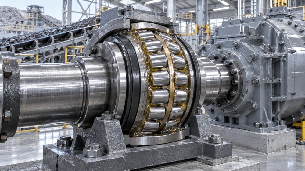
A spherical roller bearing is often a strong starting point for severe radial loading because it distributes load through rollers and can accommodate some angular misalignment. That makes it useful in applications with fabricated frames, long shafts, or variable foundation stiffness. However, self-alignment should be treated as a tolerance for real operating movement, not as permission to ignore machining accuracy or housing rigidity.
Where axial positioning and stiffness are central to machine performance, paired tapered roller bearings may be the more appropriate solution. They can support substantial combined loads, but their performance depends heavily on the correct axial setting. In shock-loaded assemblies, a setting that is acceptable at installation can change once the housing expands, the shaft deflects, or wear develops elsewhere in the stack-up.
Use load ratings correctly
Dynamic load rating is useful for estimating rolling-contact fatigue life under rotating load. It is not a complete measure of shock resistance. Static load rating is also important because it relates to permanent deformation risk when the bearing is stationary, slowly oscillating, or subjected to severe impact. A selection that meets a calculated fatigue-life target can still suffer raceway indentations if the peak event exceeds what the contact geometry can tolerate.
For each candidate bearing, evaluate both conditions separately:
- Running fatigue condition: the equivalent load during normal rotation, the speed range, operating hours, and required life.
- Peak or stationary condition: impact loads, start-up torque, blocked conveyor conditions, parking loads, oscillation, and emergency-stop events.
- Combined loading condition: radial and axial forces acting together, particularly where gears, pulleys, helical drives, or hydraulic actuators introduce thrust.
Do not apply an arbitrary safety factor without understanding what it represents. A shock allowance should reflect the actual severity and frequency of impact, uncertainty in the load path, and consequences of failure. If the machine load is poorly defined, improving the load model is usually more valuable than applying a larger multiplier to a nominal value.
The shaft and housing are part of the bearing specification
Heavy load bearings cannot compensate for inadequate supporting components. Shaft bending causes uneven roller loading. An out-of-round housing bore distorts the outer ring. A thin fabricated pedestal may flex under load and turn a nominally aligned arrangement into a permanently edge-loaded one. These conditions reduce fatigue life even if the bearing itself is correctly sized.
Review shaft diameter, shoulder geometry, fillet clearance, surface finish, and seating length. The inner ring must be supported across the intended contact width, and shoulders must locate the ring without interfering with cage or seal features. Housing bores need sufficient stiffness and appropriate geometry after welding, machining, and assembly. In large cast housings, material consistency and machining control affect how well the bearing seat holds its form over time.
Fit selection deserves particular attention. A ring carrying a rotating load generally needs an interference fit to prevent creep on its seat. Yet excessive interference reduces internal clearance, especially in large spherical roller bearings, and can raise operating temperature. The correct fit is a balance among load, ring rotation, shaft or housing material, thermal gradient, wall thickness, and planned mounting method.
Technical evaluators should request the bearing manufacturer’s fit and clearance guidance for the actual arrangement rather than copying a fit from a lighter-duty machine. This is particularly important when solid shafts are replaced by hollow shafts, steel housings replace cast housings, or the equipment uses induction heating during mounting.
Internal clearance, preload, and temperature cannot be left to assembly judgment
Clearance is the internal freedom between rolling elements and raceways before installation. During mounting, interference reduces that clearance. During operation, temperature differences between shaft, inner ring, outer ring, and housing change it again. Too little operating clearance can create heat, high friction, and smearing. Too much can reduce stiffness, increase vibration, and allow damaging roller motion under shock.
For self-aligning roller bearings, select the internal clearance class in relation to the chosen fits and expected temperature conditions. For tapered roller arrangements, define the required endplay or preload and the measurement method. “Adjust until it feels smooth” is not an acceptable specification for a critical heavy-duty assembly.
The drawing or assembly instruction should state the target condition, inspection point, and acceptance method. Depending on the design, this may be axial displacement, rotational torque, measured endplay, mounted clearance reduction, or a controlled heating-and-mounting procedure. The aim is repeatable assembly, not merely successful first installation.
Lubrication and sealing determine whether calculated life is reachable
A bearing’s calculated life assumes suitable lubrication. Shock loads make lubricant film breakdown more likely because the contact pressure rises suddenly. Low speed, oscillation, cold starts, and high temperatures can further limit film formation. Grease selection therefore cannot be reduced to choosing the highest-viscosity product available.
Specify lubricant viscosity for the operating speed and temperature, then consider base-oil type, thickener compatibility, extreme-pressure performance where appropriate, water resistance, and the relubrication method. Large bearings in remote equipment need a practical route for relubrication and a credible interval based on contamination, temperature, and duty. An automatic lubrication system may improve consistency, but only when delivery points, line routing, and grease volume are matched to the bearing arrangement.
Contamination is often the more immediate threat. Abrasive dust, scale, water, process fluid, and worn metallic particles can damage raceways long before classical fatigue life is reached. Select seals around the actual environment: contact seals, labyrinth arrangements, deflectors, bearing isolators, or multi-stage protection may be appropriate depending on speed, exposure, and permissible friction. A seal that keeps grease in but allows slurry or washdown water into the housing is not protecting the bearing system.
Check the complete arrangement, including axial freedom
A common layout uses one locating bearing position to control shaft movement and one non-locating position to allow thermal expansion. If both positions unintentionally lock the shaft, thermal growth can create axial load that was not included in the original calculation. This is especially relevant for long conveyor pulleys, heated process equipment, gearboxes, and pump shafts.
The non-locating function may be achieved through a bearing design that permits axial displacement internally or through a ring that can move in its housing under controlled conditions. The choice must be compatible with the expected shock, fit, corrosion exposure, and maintenance practice. A sliding ring arrangement that corrodes or frets in service may cease to provide the movement intended by the design.
Also examine adjacent components. Gear mesh quality, coupling alignment, belt tension, pulley overhang, hydraulic-cylinder side loads, and frame stiffness can all change the load delivered to the bearing. In power-transmission assemblies, bearing selection is therefore inseparable from the shaft, gearbox, seal, lubrication, and mounting design.
What to request before approving a supplier or bearing series
For a meaningful technical comparison, collect more than a dimensional drawing and a catalog page. The approval package should make the operating assumptions visible and allow the bearing to be traced through procurement, assembly, and maintenance.
- Complete bearing designation, dimensional envelope, and arrangement drawing.
- Radial, axial, moment, shock, speed, and duty-cycle assumptions used in the selection.
- Dynamic life calculation and a separate review of static or peak-load capacity.
- Recommended shaft and housing fits, internal clearance or preload target, and mounting procedure.
- Lubricant type, delivery method, relubrication approach, and sealing arrangement.
- Material and quality documentation appropriate to the criticality of the equipment, including traceability where required by the project.
- Inspection criteria for shaft seats, housing bores, runout, alignment, and post-installation condition.
For replacement work, investigate the failed bearing before increasing size. Raceway damage patterns can distinguish overload, contamination, electrical erosion, inadequate lubrication, creep, or misalignment. A larger bearing installed in the same distorted housing may fail in the same way, while consuming more space and cost.
Platforms such as Global Industrial Machining & Piping Equipment Network (IMPE) are useful when the review extends beyond the bearing catalog. Heavy-duty bearing performance is linked to machining tolerances, forged shaft quality, cast bearing housings, gearbox geometry, lubrication hardware, and the documentation needed for long-life industrial equipment decisions.
Make the specification executable
The final requirement should describe a working bearing system rather than a part number in isolation. State the load case, bearing arrangement, mounting fits, clearance or preload target, lubricant, sealing concept, temperature limits relevant to the machine, inspection requirements, and maintenance access. Where shock severity or load distribution remains uncertain, address that uncertainty through measurement, stronger structural validation, or supplier engineering review before release.
A bearing that is correctly selected, incorrectly fitted, poorly lubricated, or mounted in a flexible housing is not a reliable heavy-duty solution. Long service life comes from treating the rolling bearing, shaft, housing, seals, lubrication, and assembly method as one mechanical system.
Related News
- Using Industrial Air Blow Guns to Clear Chips Without Spreading DebrisOct 15, 2026Fluid Power Control Strategist
- Ductile Iron Pipe Valves: Which AWWA Standards Apply to Water Main Projects?Oct 15, 2026Dr. Elias Vance
- Why Vacuum Suction Cups Lose Grip on MDF in Woodworking MachinesOct 15, 2026CNC Kinematics Architect
- Choosing a Variable Displacement Piston Pump Manufacturer: What to VerifyOct 15, 2026Fluid Power Control Strategist
- Parallel vs. Angular Pneumatic Grippers for Confined Assembly StationsOct 15, 2026Fluid Power Control Strategist
- Die Castings vs. Investment Castings: Which Costs Less at Your Production Volume?Oct 14, 2026Foundry Phase-Change Fellow