
How Preloaded Machine Tool Bearings Improve Spindle Accuracy and Surface Finish
How Preloaded Machine Tool Bearings Improve Spindle Accuracy and Surface Finish
A spindle can have an excellent motor, a rigid housing, and a carefully balanced toolholder, yet still produce inconsistent dimensions or an unexpectedly rough finish. In many cases, the issue is not dramatic bearing failure. It is a smaller but more consequential problem: insufficient, excessive, or unstable bearing preload.
Preloaded machine tool bearings are central to how a spindle resists cutting forces, controls radial and axial movement, and behaves as speed and temperature change. For technical evaluators reviewing a machining center, spindle rebuild proposal, or bearing specification, preload should not be treated as a catalog detail. It is part of the spindle’s functional geometry. It influences runout, dynamic stiffness, vibration tendency, heat generation, lubrication demand, and ultimately the surface left on the workpiece.
The practical challenge is that preload is never evaluated in isolation. A preload value that works well in a high-speed grinding spindle may be unsuitable for a heavy milling spindle cutting forged steel. Likewise, a bearing arrangement that performs well during a short acceptance test may behave differently after a long production cycle, when the shaft, housing, lubricant, and bearing rings are all operating at different temperatures.
What Preload Actually Changes Inside a Spindle
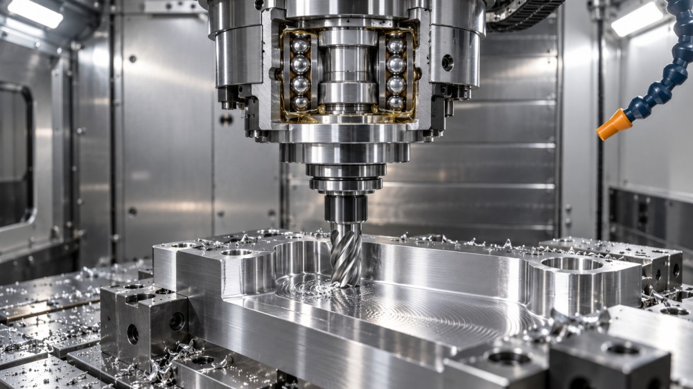
Preload is an intentional internal load applied to a bearing set before external cutting loads are introduced. In machine tool spindles, it is commonly associated with angular contact ball bearings arranged in pairs or larger groups. The arrangement may be back-to-back, face-to-face, tandem, or a combination selected to manage thrust direction, moment load, speed, and stiffness.
Without sufficient preload, there is internal clearance or a tendency for one rolling element path to unload under changing cutting forces. The spindle can then shift slightly as the tool engages the material. That movement may be very small, but at high rotational speed it can appear as waviness, chatter marks, unstable tool engagement, poor bore geometry, or inconsistent surface roughness.
Correct preload puts the rolling elements in a more stable contact condition. The spindle becomes less likely to move from one side of its internal clearance to the other when the cutter enters a corner, changes direction in a 5-axis toolpath, or encounters variable stock allowance on a casting or forging. This is particularly relevant in finishing operations, where the machine may remove only a small amount of material and any spindle displacement becomes visible on the finished surface.
There is a trade-off. Increasing preload generally increases stiffness, but it also raises contact stress and friction. More friction produces more heat; more heat changes fits and internal geometry. A spindle that is extremely stiff when cold can become thermally unstable if its preload strategy does not account for expansion during operation. That is why “higher preload” is not automatically a better specification.
Why Stiffness Has a Direct Link to Accuracy
Spindle accuracy is often discussed in terms of measured runout, but runout alone does not describe what happens during machining. A spindle may show acceptable static runout at the taper and still deflect too much when exposed to radial cutting force, axial drilling load, or an overturning moment created by a long tool projection.
Preload raises the bearing system’s resistance to displacement. In practical terms, the tool tip is less likely to move away from the intended cutting path when load changes. This helps maintain bore size, shoulder position, circularity, and wall thickness, especially on parts where the machining allowance is limited after casting, forging, or heat treatment.
The benefit is not limited to highly specialized aerospace or medical work. A machining supplier producing valve bodies, gearbox housings, hydraulic manifolds, bearing seats, forged shafts, or pump components faces the same basic issue. If the spindle has insufficient support under load, the result may be a part that appears acceptable at one measurement point but varies around the feature or changes after tool wear compensation is applied.
Bearing stiffness also interacts with the rest of the machining system. A rigid spindle cannot compensate for a weak toolholder, poor taper contact, an unbalanced cutter, an unstable fixture, or a machine column that is already near its dynamic limit. Still, spindle support is a foundational element. If the bearing set permits movement, process adjustments often become temporary workarounds rather than real corrections.
The Surface Finish Mechanism: Less Micro-Motion, More Predictable Cutting
Surface finish is affected by many variables: tool edge condition, coating, feed per tooth, workpiece material, coolant delivery, toolpath strategy, fixture stability, and machine vibration. Bearing preload does not replace control of these factors. What it does is reduce one major source of uncontrolled motion between spindle nose and cutting edge.
When preload is appropriate, the cutter remains more stable as cutting force rises and falls. The machine can follow a programmed feed path with less elastic change at the spindle. This is especially noticeable in light finishing passes, fine boring, contour milling, grinding, and machining of parts with interrupted cuts. A poorly supported spindle may leave repeating marks that resemble a tooling problem, even when the tool is new and the programming is sound.
The distinction between a bearing-related pattern and a process-related pattern is not always obvious. Repeated surface marks at a frequency linked to spindle speed, increasing vibration at particular speed ranges, or a finish that deteriorates after thermal stabilization can point toward spindle support or balance issues. By contrast, marks that closely follow tooth passing frequency may be more strongly associated with cutter geometry, tool imbalance, or cutting parameters. A meaningful diagnosis usually requires vibration data, runout checks, toolholder inspection, and review of the spindle’s temperature behavior.
Technical teams should be cautious about correcting a finish issue simply by reducing feed rate. This may hide the symptom, but it can also increase rubbing, extend cycle time, and fail to address the source of instability. If the spindle is moving under light load because preload has degraded or was incorrectly set, process changes alone will not restore consistent finishing capability.
Preload Methods and Their Operating Consequences
Machine tool spindles typically use either rigid preload or spring preload. Rigid preload is created through controlled axial positioning of matched bearings, spacers, shoulders, or clamping components. It can provide high stiffness, but it is sensitive to dimensional accuracy, mounting force, thermal growth, and assembly sequence. A small error in spacer geometry or contact condition can change the actual preload substantially.
Spring preload uses a spring mechanism to maintain force as components expand or contract. This approach can be useful where thermal compensation is important, though it may not offer the same stiffness characteristics as a rigidly preloaded arrangement. Some high-speed spindle designs use more complex systems that alter preload according to operating speed or temperature. These designs require careful control because the transition itself must remain stable and repeatable.
For evaluators, the essential question is not which method is universally superior. It is whether the selected method matches the duty cycle. A spindle intended for sustained high-speed finishing has different thermal demands from one intended for low-speed, high-torque milling of large cast iron housings. The cutting force profile, tool overhang, target surface specification, expected running time, and lubrication method all influence the right decision.
Thermal Growth Is Where Many Good Bearing Choices Go Wrong
Thermal behavior is often the deciding factor between a spindle that performs well in a controlled test and one that remains accurate through a full shift. The rotating shaft may heat faster than the housing. Lubricant temperature can change during extended operation. Motor losses, cutting heat, coolant exposure, and ambient conditions all affect the bearing environment.
If thermal expansion increases preload beyond the intended range, bearing friction rises further. This can create a self-reinforcing cycle of heat, expansion, and higher contact load. The early signs may be rising spindle temperature, a change in vibration signature, reduced grease life, or gradual loss of surface consistency. In severe cases, the bearing may suffer raceway damage or cage distress, but a process capability problem usually appears earlier than visible bearing failure.
Conversely, if the arrangement loses preload as the spindle warms, stiffness can fall during production. Operators sometimes describe this as a machine that cuts well after setup but loses size or finish later in the run. It is not always a bearing problem, yet temperature-dependent behavior should prompt a review of bearing arrangement, fits, lubrication quantity, cooling circuit performance, and spindle warm-up procedure.
A sensible technical assessment includes cold-start and stabilized-condition measurements. Static taper runout, housing temperature, shaft-related temperature indications where available, vibration levels, and test-cut results should be compared over time rather than recorded only once. The exact acceptance method should follow the machine builder’s documentation, applicable customer requirements, and the relevant measurement standard for the component or finished feature.
Lubrication, Cleanliness, and Installation Are Part of the Preload System
Preload is often specified at assembly, but its useful life depends heavily on lubrication and contamination control. In grease-lubricated spindles, excess grease can generate heat through churning, while insufficient grease can allow damaging metal-to-metal contact. Oil-air and oil-mist systems have their own requirements for dosage, air quality, distribution, and line condition. The right lubricant quantity is not a generic maintenance setting; it depends on spindle design and supplier guidance.
Contamination is equally unforgiving. Fine abrasive particles, coolant ingress, poor sealing, or debris introduced during assembly can damage raceway surfaces and disrupt smooth rolling contact. As damage develops, preload may become uneven around the rotation, producing noise, vibration, and surface artifacts that are hard to diagnose from the finished part alone.
Installation quality deserves the same level of attention as the bearing grade. Angular contact bearings should be handled as matched components when supplied as a set. Orientation marks, spacer identification, shaft and housing fits, shoulder squareness, tightening sequence, and cleanliness of contact faces all matter. Driving force through the wrong ring during mounting can create brinelling or other damage before the spindle ever runs. Bearing tolerance references such as ISO 492 may support dimensional review, but spindle assembly requirements must still come from the bearing manufacturer and spindle design documentation.
What to Review Before Approving a Spindle Bearing Specification
A bearing designation alone is not enough for a technical approval. It identifies a component family, not the complete operating result. Procurement and engineering teams should request enough information to understand how the bearing set works within the spindle rather than comparing catalog entries only by size, speed rating, or unit cost.
- Bearing arrangement and contact-angle selection, including how radial, axial, and moment loads are carried.
- Preload class or target preload method, with confirmation of whether preload is fixed, spring-controlled, or variable.
- Expected operating speed range and the thermal strategy used at sustained speed.
- Lubrication type, replenishment approach, sealing arrangement, and contamination-control provisions.
- Requirements for matched bearings, spacers, fits, assembly force, and post-assembly inspection.
- A practical verification plan covering warm-up, vibration, temperature, runout, and representative cutting conditions.
For machinery producers and repair teams, this review is especially valuable when a spindle is being adapted to a new material family or duty cycle. A machine originally used for aluminum finishing may need a different support strategy if it is reassigned to interrupted cutting in ductile iron, stainless steel, or forged alloy components. The bearing system should be evaluated together with torque demand, tool mass, cutter engagement, coolant conditions, and production duration.
A Better Way to Judge Bearing Value
The value of preloaded machine tool bearings is not simply that they make a spindle feel tighter. Their value is that they make spindle behavior more predictable under real machining loads. That predictability supports stable dimensions, more repeatable finishing, and earlier detection when lubrication, thermal control, alignment, or assembly quality begins to drift.
Within precision machining and the wider industrial component supply chain, bearing evaluation should connect mechanical details to the finished part: bore geometry in a hydraulic block, sealing-face quality on a valve body, concentricity of a forged shaft, or fit accuracy in a gearbox housing. IMPE’s broader equipment perspective is useful here because spindle performance is rarely a single-component question. Bearings, tooling, machine structure, lubrication, inspection discipline, and process selection all meet at the cutting edge.
When preload is selected for the actual load and speed profile, installed with disciplined control, and checked after thermal stabilization, it becomes a quiet source of machining capability. When it is treated as an afterthought, surface finish and accuracy are often the first places where the cost becomes visible.
Related News
- How to Assess a Rigid Coupling Supplier for Bore Accuracy and Traceable QualityOct 08, 2026Tribology & Kinematics Expert
- Titanium Alloys Compared: Balancing Strength, Corrosion Resistance, and MachinabilityOct 08, 2026CNC Kinematics Architect
- Where Ductile Iron Dismantling Joints Reduce Alignment Risk in Water PipelinesOct 08, 2026Pipeline Metallurgy Scientist
- Selecting a Precision Bearing Sleeve: Fits, Runout, and Material ChoicesOct 08, 2026Tribology & Kinematics Expert
- Face Milling Cutters: How Insert Geometry Affects Finish on Steel and AluminumOct 08, 2026CNC Kinematics Architect
- Single-Acting Cylinders for Clamping: Stroke, Force, and Return Spring ConsiderationsOct 07, 2026Fluid Power Control Strategist