
How Low-Runout Precision Bearings Protect Surface Finish in Machine-Tool Spindles
How Low-Runout Precision Bearings Protect Surface Finish in Machine-Tool Spindles
Surface finish problems are often traced to feeds, speeds, tool geometry, coolant delivery, or workpiece material. Those factors matter, but they do not fully explain a recurring pattern seen in precision machining: a process that appears stable on paper still produces waviness, chatter marks, inconsistent gloss, or dimensional variation from one tool change to the next. In many cases, the spindle’s rotating accuracy is part of the underlying problem.
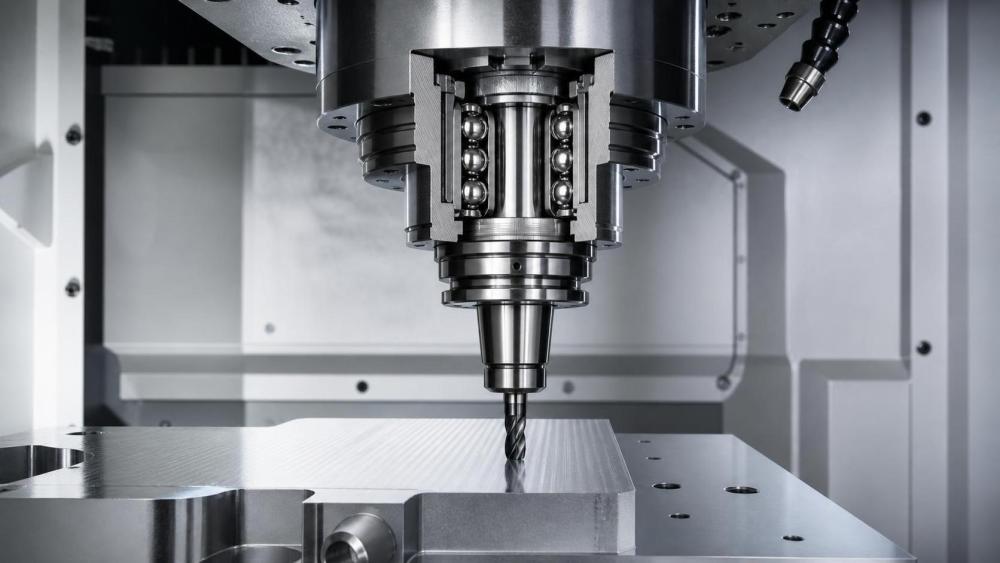
Low-runout precision bearings are central to how a machine-tool spindle maintains a stable tool centerline during rotation. Their purpose is not simply to support a shaft or carry a load. In a high-speed milling, grinding, drilling, or turning spindle, bearing geometry, internal clearance or preload, fit condition, lubrication, and thermal behavior all influence the radial and axial motion transmitted to the cutting edge. Even a small deviation at the spindle nose can become visible on a finished surface, particularly when tool diameter is small, tolerances are tight, or the operation has little allowance for secondary finishing.
For technical evaluators, the useful question is not whether a bearing is described as “precision grade.” The question is whether the complete bearing arrangement can preserve concentric rotation under the actual combination of speed, cutting load, tool overhang, thermal growth, lubrication condition, and assembly quality expected in service.
Runout is a system condition, not a bearing catalog number
Runout is commonly understood as the variation of a rotating surface relative to a reference axis. In a spindle, the observed value at the toolholder taper, gauge line, test arbor, or cutting edge is the accumulated outcome of several contributors. Bearing radial runout is one contributor, but it exists alongside shaft form error, housing bore geometry, bearing-seat roundness, shoulder squareness, toolholder taper condition, drawbar force, toolholder balance, assembly cleanliness, and measurement method.
This distinction prevents a common purchasing error: specifying a highly accurate bearing while treating the spindle shaft, housing, and assembly controls as ordinary production details. A low-runout bearing installed on a distorted seat cannot deliver its intended rotating accuracy. Likewise, a spindle may measure acceptably at the nose with no cutting load, then show a poor surface under machining because preload shifts with temperature or a long tool amplifies a small motion at the bearing location.
The relevant engineering objective is therefore assembled spindle rotational accuracy. Bearing selection should be evaluated as part of a rotating system rather than as an isolated component comparison.
Why surface finish responds so strongly to spindle motion
An ideal cutting tool follows a predictable path and removes material with a consistent chip load. Radial runout changes that path. On a multi-flute end mill, one flute may remove more material than the others because its effective radius is slightly larger. The resulting uneven tooth loading can leave periodic marks, accelerate localized edge wear, and increase the chance of vibration. In finishing passes, the visible result may be a repeated pattern rather than a uniformly machined surface.
The effect is particularly noticeable in small-diameter tools, reamers, micro-drills, boring tools, and grinding applications. These tools have limited stiffness and may operate with a fine radial engagement. A modest displacement at the spindle interface can represent a meaningful portion of the programmed chip thickness. Rather than cutting consistently, the tool may rub intermittently, deflect, or engage unevenly. Surface quality then deteriorates even though the CNC program has not changed.
Axial motion also matters. Face milling, boring, drilling, and precision grinding can show axial waviness or inconsistent floor finish when the rotating assembly does not maintain stable axial position. A spindle bearing set must resist combined radial and axial loads while retaining the intended contact geometry. This is one reason angular-contact ball bearings are widely used in precision machine-tool spindles: when correctly selected and preloaded, they can provide axial stiffness as well as radial support. Their suitability, however, depends on the arrangement, speed range, load direction, and thermal design.
The bearing arrangement determines how runout behaves in production
A machine-tool spindle normally uses more than one bearing, often arranged as matched sets at the front and rear of the shaft. The front set governs stiffness and positional stability near the cutting zone; the rear support helps control shaft behavior and accommodate the design’s thermal strategy. Arrangement choices such as back-to-back, face-to-face, tandem, or combinations of these are not interchangeable. Each creates a different response to overturning moment, axial load direction, and thermal expansion.
For example, a long toolholder and a side-milling operation generate an overturning moment at the spindle nose. The front bearing spacing and contact-angle arrangement influence how effectively the spindle resists that moment. If support is insufficient for the intended cutting condition, the tool tip can move even where unloaded runout appears controlled. That movement is not always a simple once-per-revolution error; it may interact with structural modes in the machine, toolholder, fixture, and workpiece.
Preload is equally important. It removes internal play and increases stiffness, but greater preload also raises friction and heat generation. At high speed, excessive preload can create thermal growth, alter contact conditions, shorten lubricant life, and eventually undermine the accuracy it was meant to improve. Too little preload can allow motion under changing cutting loads. The right condition is therefore application-specific, not automatically “as tight as possible.”
Precision classes and standards: useful, but incomplete
Bearing standards provide a necessary common language. ISO 492 specifies tolerances for radial bearings, while ISO 1132 addresses measuring methods for rolling bearings. In procurement and technical documentation, bearing manufacturers may also use precision-class designations associated with ISO systems or national systems such as ABEC classifications. These references are valuable because they define allowable variation in dimensions and running accuracy under specified measurement conditions.
They should not be read as a direct guarantee of spindle-nose runout or machined surface roughness. A bearing’s stated tolerance class describes the bearing under defined inspection conditions; it does not capture every assembly influence in a machine tool. Technical teams should confirm which characteristic is being quoted: inner-ring radial runout, outer-ring runout, bore variation, width variation, or assembled spindle measurement. These are related but not identical values.
The same caution applies to surface finish targets. Surface roughness parameters such as Ra, Rz, and Rt describe different aspects of a measured profile and depend on cutoff settings, instrument configuration, machining direction, workpiece material, and process stability. It is not technically sound to state that a particular bearing grade will produce a particular Ra value without validating the complete machining system.
A stronger specification links requirements in sequence: required part geometry and surface condition; expected cutting loads and speeds; acceptable spindle interface motion; bearing arrangement and preload; component tolerances; then inspection and acceptance methods. This creates traceability from part-quality risk back to the mechanical design decision.
Where low-runout bearings make the clearest difference
The value of low-runout precision bearings is most evident where the spindle is asked to do more than remove bulk material. Finishing passes on mold cavities, precision bores, bearing seats, sealing faces, optical-adjacent components, and thin-walled parts demand stable cutting engagement. In aerospace, medical-device, robotics, energy, and high-end automation work, repeatability may matter as much as the finish from a single sample part. A spindle that remains stable across a production shift reduces the risk of compensating one process variable while another quietly changes.
Grinding spindles present another demanding case. Abrasive processes can be highly sensitive to vibration and wheel imbalance, while the desired surface may reveal defects that are less obvious in general milling. Here, bearing rotational accuracy must be considered with wheel mounting, balancing practice, spindle housing stiffness, thermal control, and dressing conditions.
That does not mean every machining center needs the highest available bearing precision. A roughing spindle handling large cutters at moderate speed may be governed more by load capacity, contamination resistance, rigidity, and serviceability. Over-specifying bearing precision without controlling the surrounding interfaces can increase cost while leaving the actual finish problem unresolved.
Inspection should separate bearing problems from tooling problems
When surface defects appear, technicians often measure runout at a tool tip and stop there. That reading is useful, but it combines multiple interfaces. A more informative investigation moves from the spindle outward: inspect the spindle taper or nose interface, then a qualified test arbor, then the toolholder, then the cutting tool. Measurements should be taken with a documented setup and at positions that reflect the actual overhang where practical.
Warm-up condition must also be recorded. A measurement made immediately after start-up may not represent a spindle after sustained high-speed operation. If the machine is designed for thermal stabilization, the inspection plan should state the speed, duration, ambient conditions, lubricant state, and any cooling-system conditions used before acceptance readings are taken. Without this context, two technically correct measurements can appear contradictory.
Vibration analysis can complement runout measurement, especially when the surface pattern is periodic or appears only within a particular speed band. It can help distinguish geometric eccentricity from imbalance, resonance, damaged rolling elements, poor lubrication, or toolholder-related excitation. The interpretation still requires care: a vibration signature is evidence to investigate, not a standalone diagnosis.
Procurement questions that reveal real spindle capability
For OEM engineering teams and technical buyers, a bearing quotation alone rarely provides enough information for a high-accuracy spindle decision. The discussion should cover the intended speed range, load spectrum, duty cycle, lubrication system, mounting arrangement, preload method, housing and shaft fit tolerances, and expected operating temperature. If bearings are supplied as matched sets, confirm how set matching, orientation, handling, and traceability are controlled.
It is also worth asking how the spindle builder verifies assembled runout and whether the acceptance method matches the application. A test arbor at the nose may be appropriate for one machine, while a process-oriented test cut or grinding trial may be needed to understand final surface risk. Neither method replaces the other; they answer different questions.
Documentation should be proportional to the consequence of failure. For critical production equipment, technical evaluators may need dimensional inspection records, material and bearing traceability where required, lubrication guidance, installation instructions, and clear limits on storage and handling. These details are less visible than a precision-class label, yet they often decide whether low-runout capability survives transport, assembly, and operation.
A practical conclusion for spindle evaluation
Low-runout precision bearings protect surface finish by reducing one of the most consequential sources of unwanted tool motion. They help maintain consistent cutting engagement, distribute load more predictably across cutting edges, and support repeatable spindle behavior. But their benefit is realized only when the spindle is designed, manufactured, assembled, lubricated, and inspected as a controlled system.
This systems view is relevant across the machining and power-transmission topics covered by Global Industrial Machining & Piping Equipment Network (IMPE). Whether the component is a high-speed spindle, forged shaft, gearbox, hydraulic unit, or ductile iron piping assembly, the visible result depends on how tolerances, material behavior, interfaces, and service conditions interact. For a spindle project, the most reliable next step is to define the required surface and geometric outcome first, then verify that bearing accuracy, arrangement, thermal behavior, tooling interfaces, and inspection methods all support that requirement.
Related News
- How to Assess a Rigid Coupling Supplier for Bore Accuracy and Traceable QualityOct 08, 2026Tribology & Kinematics Expert
- Titanium Alloys Compared: Balancing Strength, Corrosion Resistance, and MachinabilityOct 08, 2026CNC Kinematics Architect
- Where Ductile Iron Dismantling Joints Reduce Alignment Risk in Water PipelinesOct 08, 2026Pipeline Metallurgy Scientist
- Selecting a Precision Bearing Sleeve: Fits, Runout, and Material ChoicesOct 08, 2026Tribology & Kinematics Expert
- Face Milling Cutters: How Insert Geometry Affects Finish on Steel and AluminumOct 08, 2026CNC Kinematics Architect
- Single-Acting Cylinders for Clamping: Stroke, Force, and Return Spring ConsiderationsOct 07, 2026Fluid Power Control Strategist