
Choosing Tapered Roller Bearings for Wheel Hubs Under Heavy Radial and Axial Loads
For wheel hubs exposed to heavy loads, the bearing choice should begin with the load path, not with a catalog bore diameter. Tapered roller bearings for wheel hubs are often selected because they can carry substantial radial load while also resisting axial force. That combination is valuable in truck axles, trailers, agricultural machinery, construction equipment, mining vehicles, industrial transport systems, and other applications where wheel loads are rarely purely vertical.
A bearing that appears adequate on its basic dynamic load rating can still fail early if preload, hub stiffness, sealing, lubrication, or mounting fits are wrong. The reliable choice is the bearing arrangement that maintains roller contact, running clearance, lubricant condition, and seal performance through the real operating cycle: loaded travel, cornering, braking, vibration, impact, temperature change, and long idle periods.
Start with the forces acting on the hub
A wheel hub normally imposes both radial and axial loading on its bearings. Radial load comes from vehicle weight, payload, uneven ground, and vertical impact. Axial load is generated by cornering, steering geometry, side slopes, wheel offset, braking forces, and, in some driven systems, gear or shaft reactions. These forces do not act independently. A heavily loaded wheel striking an obstacle while turning can create a much more demanding condition than steady travel on level ground.
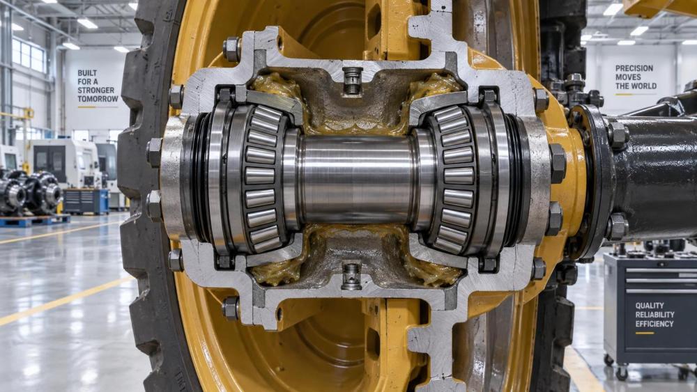
Tapered roller bearings are well suited to this duty because the rollers and raceways are angled. The contact geometry allows the bearing to transmit a combined load rather than treating axial force as an unwanted side effect. In a typical hub assembly, two bearings are mounted in opposition so that one bearing can support axial force from one direction and the other supports force from the opposite direction.
The arrangement matters as much as the individual bearing. A wide bearing spread improves the hub’s ability to resist overturning moment, which is the tilting force caused when the wheel load acts away from the bearing centerline. This is especially relevant for wide wheels, offset rims, long hubs, and equipment that travels over rough surfaces. Selecting a larger bearing without considering bearing spacing may not solve a moment-load problem.
Do not size from static weight alone
Using axle weight or rated payload as the only selection input is a common error. The wheel hub may see short-duration loads far above its normal parked load because of potholes, curbs, uneven tracks, loose material, abrupt braking, or cyclic lifting and dumping operations. Repeated shock events can damage raceways and rollers even when the average duty looks moderate.
The selection review should separate at least four conditions:
- Normal operating load: the expected radial and axial force during ordinary service.
- Peak or shock load: impact and transient events that can produce brinelling, surface distress, or permanent deformation.
- Duty cycle: travel speed, operating hours, direction changes, stops, and loaded versus unloaded time.
- External moment: the effect of wheel offset, hub geometry, and the distance between the two bearing positions.
Dynamic capacity is relevant when fatigue life is the principal concern. Static capacity becomes equally important where equipment is parked under load, moves slowly over harsh ground, receives repeated impacts, or can experience severe brief overloads. Neither value should be interpreted in isolation. The applied load must be converted into the load carried by each bearing within the actual hub geometry.
When reliable field-load data is unavailable, the practical approach is to define credible operating envelopes rather than rely on an idealized single load case. Consider maximum payload, the most severe expected terrain, the largest wheel and tire combination, braking events, and the most demanding steering or side-load condition. This produces a more useful basis for comparing bearing options and hub layouts.
Choose the bearing arrangement before finalizing the bearing series
Most heavy-duty wheel hubs use a paired arrangement. Two commonly used layouts are commonly described as back-to-back and face-to-face. Their real distinction is the direction in which the effective load lines spread across the hub.
The best layout cannot be selected from this comparison alone. Hub stiffness, spindle stiffness, axle deflection, seal locations, assembly access, and service method all influence the result. What should be avoided is treating two opposing single-row bearings as interchangeable parts that can be reversed without changing system behavior.
For compact assemblies, a matched unit or an integrated hub-bearing solution may reduce adjustment variability and simplify assembly. Separate cone-and-cup components, however, remain useful where serviceability, nonstandard dimensions, high capacity, or custom hub design are priorities. The right decision depends on whether the application values controlled factory assembly or field-replaceable components.
Preload and endplay determine whether the bearing works as intended
A correctly sized bearing can run too hot, loosen quickly, or develop early damage if axial setting is wrong. Tapered roller bearings require controlled internal clearance through either preload or a defined endplay condition. This setting determines how the rollers contact the raceways when the hub is operating.
Excessive preload raises friction and temperature. It can thin the lubricant film, accelerate cage and roller wear, and cause damage that may initially resemble a lubrication problem. Too much endplay allows movement in the hub, promotes vibration, changes seal contact, and can create uneven roller loading. In severe cases, looseness produces wheel wobble and raceway damage.
The target setting is not universal. It changes with bearing size, bearing spacing, hub and spindle material, fit interference, expected operating temperature, lubricant type, and the degree of structural deflection under load. A setting that performs well in a moderate-duty trailer hub may be unsuitable for a high-speed industrial vehicle or a heavily loaded off-road axle.
Adjustment method also deserves review. A nut-and-locking system can be practical for serviceable hubs, but it depends on a repeatable assembly procedure and proper retention. Spacer-controlled systems can improve consistency when parts are produced to controlled dimensions. In either case, the procedure should account for seating the bearing components before the final setting is measured. Measuring a hub before the rollers and cups are fully seated creates a misleading result.
Lubrication and sealing are part of bearing selection
Wheel hub bearing life is strongly affected by contamination and lubricant condition. Dust, water, metallic debris, and abrasive particles can damage the contact surfaces long before the bearing reaches its calculated fatigue life. For equipment used in washdown areas, wet construction sites, agricultural work, coastal environments, or dusty material handling, the sealing package may be the limiting factor rather than the bearing’s nominal load capacity.
Grease-lubricated hubs need a lubricant with suitable consistency, base oil behavior, and resistance to the operating environment. The grease must reach the roller contacts without excessive churning. Overfilling is not automatically protective: high fill levels can increase temperature and disturb seal performance, particularly at higher rotational speeds. Underfilling or neglected relubrication leaves the contact zone exposed to starvation and contamination.
Oil-lubricated hubs can offer effective heat removal and monitoring opportunities, but they require dependable oil retention and a controlled level. Seal choice must reflect shaft surface condition, speed, runout, pressure variation, and environmental exposure. A seal that works during clean, steady operation may fail when mud packing, pressure washing, or hub misalignment is introduced.
Specify the complete sealing path, including outer seals, inner seals, grease caps or covers, venting strategy where applicable, and the condition of the mating surfaces. A premium bearing installed behind an unsuitable seal is still a vulnerable assembly.
Fits, seats, and component stiffness should be checked on the drawing
Bearings do not operate directly on a drawing nominal. They operate on real shafts, bores, shoulders, fillets, spacers, and clamping faces. The cone must be supported properly on the spindle, and the cup must be firmly seated in the hub bore. Insufficient interference can allow creep, fretting, and heat generation. Excessive interference can reduce internal clearance, distort thin rings, and complicate service removal.
The geometry around the bearing is equally important. Shoulder height must locate the ring without interfering with the cage or chamfer. Fillet radii must be compatible with the bearing chamfer. Spacer faces need adequate flatness and parallelism so they do not introduce tilt. Hub bores should maintain roundness and surface quality appropriate to the fit; an out-of-round bore can distort the outer ring and concentrate load on part of the raceway.
This is where machining and casting quality affect bearing performance directly. In heavy equipment, a strong bearing cannot compensate for a poorly controlled bearing seat, inadequate hub rigidity, or a spindle that deflects excessively. Drawing review should therefore include the surrounding machined features and not only the bearing part number.
Material quality and supplier evidence matter in high-consequence hubs
For demanding wheel applications, evaluation should extend beyond dimensions and stated ratings. Ring and roller material cleanliness, heat treatment consistency, raceway finish, cage design, and traceability influence reliability under cyclic stress and contaminated lubrication. The purpose is not to demand unnecessary documentation; it is to make sure the evidence matches the consequences of failure and the service environment.
A procurement comparison is more useful when it asks for information that can be reviewed against the hub design: dimensional inspection records, material and heat-treatment traceability where required, declared internal geometry or matched-set information, packaging controls, and clarity on lubrication and mounting guidance. Consistency across production lots matters particularly for fleets, OEM programs, and repair networks that depend on repeatable adjustment behavior.
IMPE’s coverage of bearings, forged shafts, machined components, sealing, and power-transmission assemblies reflects this systems view. A wheel hub should be evaluated as an assembly in which bearing capacity, spindle integrity, machined tolerances, lubrication control, and maintenance practice support one another.
When tapered roller bearings may not be the best answer
Tapered roller bearings are a strong choice for combined radial and axial wheel loads, but they are not automatically the preferred option for every rotating wheel. Applications with very high rotational speed, low axial load, strict friction targets, or a need for a sealed maintenance-free package may favor another bearing architecture. Compact automotive-style hubs, for example, may be better served by purpose-designed integrated units when the load, stiffness, sensor, sealing, and assembly requirements support that choice.
The question is not whether tapered rollers are generally better than other bearings. It is whether their adjustability, load capability, serviceability, and combined-load behavior fit the actual wheel hub duty. A technically sound evaluation compares complete assembly behavior, not isolated bearing features.
Use this selection sequence before releasing the design
- Define radial load, axial load, peak shock, speed range, operating temperature, and expected service cycle.
- Review wheel offset, bearing spacing, and resulting overturning moment.
- Select the bearing arrangement and determine how each bearing shares combined load.
- Check dynamic life, static load resistance, and stiffness against the governing operating conditions.
- Set the preload or endplay strategy, including the production or service adjustment method.
- Specify lubricant, seals, relubrication access, and contamination protection as a single system.
- Verify spindle and hub fits, shoulders, radii, bore geometry, spacer faces, and clamping details.
- Request supplier documentation that supports dimensional consistency, material control, and traceability appropriate to the application.
A wheel hub bearing decision is complete only when the bearing, hub, spindle, seals, lubricant, and adjustment method have been reviewed together. That approach prevents the common outcome in which a higher-capacity bearing is installed, yet the underlying problem remains misalignment, incorrect setting, contamination, or structural deflection.
Related News
- How to Assess a Rigid Coupling Supplier for Bore Accuracy and Traceable QualityOct 08, 2026Tribology & Kinematics Expert
- Titanium Alloys Compared: Balancing Strength, Corrosion Resistance, and MachinabilityOct 08, 2026CNC Kinematics Architect
- Where Ductile Iron Dismantling Joints Reduce Alignment Risk in Water PipelinesOct 08, 2026Pipeline Metallurgy Scientist
- Selecting a Precision Bearing Sleeve: Fits, Runout, and Material ChoicesOct 08, 2026Tribology & Kinematics Expert
- Face Milling Cutters: How Insert Geometry Affects Finish on Steel and AluminumOct 08, 2026CNC Kinematics Architect
- Single-Acting Cylinders for Clamping: Stroke, Force, and Return Spring ConsiderationsOct 07, 2026Fluid Power Control Strategist