
Choosing Cylindrical Roller Bearings for High-Speed Electric Motor Loads
Selecting cylindrical roller bearings for electric motors begins with a practical question: is the bearing being asked to carry mainly radial load at high rotational speed, while allowing the shaft to expand as temperature changes? When the answer is yes, a cylindrical roller bearing can be an effective choice. Its line contact between rollers and raceways supports high radial loads with good stiffness, and many designs allow axial displacement between the inner and outer rings.
That does not mean any bearing with a suitable bore diameter and catalog load rating will work. High-speed motors expose weaknesses in lubrication, cage performance, fit selection, balance quality, and mounting accuracy. A bearing that appears adequate in a static calculation can still run hot, generate excessive vibration, or fail early when installed in a motor with rapid starts, variable-frequency operation, belt loading, or a tightly enclosed housing.
The sound selection approach is to define the complete bearing position in the motor, not to select the bearing as an isolated component. Load direction, shaft expansion, rotor dynamics, operating speed, temperature, lubrication method, contamination exposure, and the function of the bearing at the opposite end all need to be considered together.
Start with the bearing arrangement, not the bearing series
In many electric motors, one bearing position must locate the rotor axially, while the other must permit axial movement caused by thermal growth. A cylindrical roller bearing is frequently used at the non-locating end because certain designs can accommodate displacement internally. This prevents the bearing arrangement from becoming axially preloaded as the shaft and housing reach different operating temperatures.
This benefit depends on the specific bearing design. A cylindrical roller bearing with ribs on both rings can guide the rollers axially but has limited freedom for shaft expansion. A design with a ribless ring may allow one ring to move relative to the roller-and-raceway assembly, making it better suited to a floating position. The bearing designation alone is not enough; the selected internal geometry must match the intended locating or non-locating function.
A common mistake is placing two effectively locating bearings into a motor without confirming thermal movement. At assembly temperature, the motor may turn freely. Once energized, expansion can create axial stress, raise friction, and alter running clearance. The resulting damage may resemble a lubrication problem even though the original cause is an incorrect bearing arrangement.
Radial load capacity is only one part of the decision
Cylindrical roller bearings are well suited to substantial radial loading from rotor weight, magnetic pull, belt drives, gears, couplings, or process equipment. Their roller contact distributes radial force across a larger contact area than a ball bearing. This can make them attractive for motors driving fans, pumps, conveyors, compressors, gearboxes, and other equipment where shaft bending is meaningful.
However, the actual radial load must be evaluated at the bearing location. A belt drive may create a much larger overhung load than expected, especially when pulley position, belt tension, and motor mounting geometry are considered together. A coupling that appears flexible can still transmit radial force if shaft alignment is poor. In vertical motors, rotor weight and thrust conditions also require separate review.
Load ratings should therefore be treated as a screening tool rather than a complete selection result. The bearing should have sufficient fatigue life under the expected duty cycle, but it must also maintain appropriate internal clearance and stable motion at operating speed. Selecting an oversized bearing only for load capacity can increase friction, complicate lubrication, and create fit or clearance problems.
Speed capability depends on heat generation and cage behavior
High speed does not simply mean checking the maximum permissible rotational speed listed in a catalog. That value is influenced by bearing size, cage type, lubrication, preload or clearance, heat removal, and the accuracy of surrounding parts. The relevant question is whether the complete motor can operate with stable bearing temperature and acceptable vibration at its highest continuous speed and during acceleration.
The cage deserves particular attention. The cage spaces the rollers, controls their motion, and helps prevent roller-to-roller contact. At higher speeds, its material, guidance method, strength, and compatibility with the lubricant affect running behavior. A cage suitable for a general-purpose motor may not be the preferred option for a compact high-speed machine with elevated temperature or rapid speed changes.
There is also a practical tradeoff between robustness and speed. Bearings designed for high radial capacity may use more or larger rollers, while designs intended for higher speed may favor geometry and cage arrangements that reduce friction and roller mass effects. Neither is automatically superior. The correct option follows the real combination of load, speed, lubrication, and service life requirement.
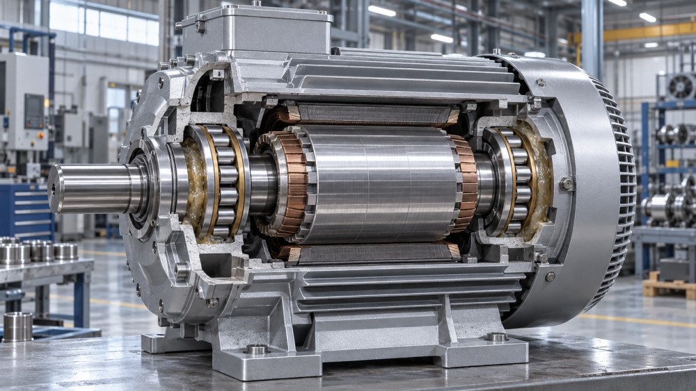
Internal clearance must be selected for operating conditions
Internal radial clearance is often treated as a catalog detail, but it strongly influences bearing temperature, stiffness, noise, and fatigue performance. The clearance measured before mounting is not the clearance available during operation. An interference fit on the shaft expands the inner ring. A warm rotor can expand it further. Housing temperature, external load, and the temperature difference between rings also affect the final running condition.
Too little operating clearance can lead to high friction, overheating, smearing, and rapid lubricant deterioration. Too much clearance can reduce guidance accuracy, increase vibration, and make the motor more sensitive to rotor imbalance or electromagnetic excitation. The target is a suitable operating clearance after mounting and thermal stabilization, not a clearance class chosen by habit.
Fit decisions are linked directly to this calculation. The ring exposed to a rotating load zone generally needs enough interference to prevent creep on its seat. Ring creep can wear the shaft or housing, produce fretting debris, and make later removal difficult. Yet an unnecessarily heavy interference fit can consume critical internal clearance and introduce hoop stress into the ring.
For this reason, bearing selection should be reviewed alongside shaft and housing tolerances, surface finish, seat length, roundness, and shoulder geometry. A correctly specified bearing cannot compensate for an oval housing bore, a damaged shaft seat, or a shoulder that contacts the cage or roller path.
Lubrication is part of the design, not a maintenance afterthought
Grease lubrication is common in electric motors because it is compact and simple, but a high-speed application must account for grease churning and heat. Excess grease can create substantial friction during startup and operation. Too little grease, unsuitable base oil viscosity, weak oxidation resistance, or poor relubrication practice can leave the roller contacts inadequately protected.
Oil lubrication may be appropriate where speed, temperature, or service conditions justify a more controlled system. It can remove heat more effectively and provide a continuous lubricant supply, but it introduces requirements for sealing, oil cleanliness, circulation, and leakage control. The right choice is determined by the motor design and maintenance environment, not by an assumption that one lubricant type is inherently more advanced.
The lubricant must form an adequate film under the actual contact conditions. At low speed, film formation can be less favorable. At very high speed, churning, air entrainment, and temperature rise can become more important. Variable-frequency motors complicate this further because they may spend time at low speed, pass repeatedly through critical vibration ranges, and operate above a traditional line-frequency speed.
Contamination control has the same importance as lubricant selection. Fine particles, moisture, cleaning fluid, and degraded grease can damage rolling surfaces long before a calculated fatigue life is reached. The sealing arrangement should be evaluated with the environment in mind: a lightly protected indoor motor has different needs from a motor exposed to washdown, dust, outdoor humidity, or conductive process contamination.
Do not use a cylindrical roller bearing to solve every motor load problem
These bearings primarily excel under radial load. They can carry some axial load in designs with guiding ribs, but their axial capability is not a substitute for a dedicated thrust-bearing arrangement when the motor experiences sustained or substantial thrust. Vertical pumps, screw compressors, and machinery with process-generated axial force require a clear review of thrust direction, magnitude, reversals, and the bearing that will locate the rotor.
Misalignment is another boundary. Cylindrical roller bearings generally tolerate less angular misalignment than self-aligning bearing types. Minor elastic deflection may be acceptable within the bearing manufacturer’s guidance, but housing distortion, shaft bending, or poor end-shield machining can concentrate load at one end of the rollers. This produces edge stress, heat, and premature raceway damage.
Where alignment cannot be controlled, the answer may be to improve the motor housing and machining process, change the support arrangement, or select a bearing type with better misalignment tolerance. Replacing a bearing with a higher-capacity cylindrical roller design does not correct a structural alignment problem.
Vibration, electrical effects, and noise need an explicit review
High-speed motors are sensitive to rotor balance, fan forces, electromagnetic excitation, and resonance in the shaft-bearing system. Bearing radial clearance, raceway accuracy, cage stability, and mounting quality all influence the vibration result. A bearing selected solely for basic load capacity can meet a life calculation yet still be unsuitable for a motor where smooth running and low vibration are functional requirements.
Electrical discharge through bearings is also relevant in motors driven by variable-frequency inverters. Shaft voltage can damage rolling contacts and produce characteristic fluting or surface distress. This is not solved by changing grease or increasing bearing size. The motor system may need electrical insulation at an appropriate bearing position, shaft grounding, or other measures matched to the drive and grounding arrangement.
Noise requirements should be stated early, particularly for HVAC equipment, machine tools, robotics, laboratory equipment, and enclosed industrial systems. Noise can come from bearing geometry, lubricant condition, excessive clearance, contaminated raceways, structural resonance, or rotating-component imbalance. The bearing specification should be coordinated with the required motor quality level rather than added late in procurement.
A practical comparison process before release
A disciplined selection review can prevent most avoidable bearing mismatches. It should start with the motor’s load path and operating envelope, then move toward detailed bearing and manufacturing requirements.
- Map each bearing position. Define which end locates the rotor and which end absorbs thermal displacement. Identify all radial and axial loads acting at each position.
- Establish the operating range. Use maximum continuous speed, normal speed, acceleration profile, start-stop frequency, ambient temperature, and expected duty cycle rather than relying only on nameplate speed.
- Assess shaft and housing behavior. Review seat dimensions, tolerances, roundness, surface finish, housing stiffness, expected temperature difference, and thermal expansion.
- Select the internal design. Compare roller arrangement, flange configuration, cage type, clearance class, and lubricant compatibility against the required speed and load conditions.
- Check the surrounding system. Consider belt or gear forces, coupling alignment, rotor balance, vibration limits, sealing, contamination exposure, and inverter-related electrical risks.
- Define procurement evidence. Drawings, material and quality documentation, inspection expectations, traceability, packaging, and supplier technical support should match the importance of the motor application.
For motors used in power transmission assemblies, the bearing cannot be separated from the shaft, housing, coupling, seals, and driven equipment. IMPE’s industrial component coverage is useful in this context because bearing selection is often a system-level review of machining tolerances, material behavior, lubrication, alignment, and long-term maintainability rather than a single catalog comparison.
Questions that expose weak selections
Can a larger cylindrical roller bearing always improve motor life?
No. A larger bearing may raise load capacity, but it can also increase friction, mass, lubricant churning, and installation complexity. The better selection is the bearing that achieves the required life and stiffness while remaining thermally stable at the intended speed.
Should a high-speed motor use tighter internal clearance for better stiffness?
Not automatically. A tight initial clearance can become insufficient after interference fitting and thermal expansion. Stiffness matters, but the bearing still needs appropriate running clearance to avoid heat and contact stress.
Is grease type interchangeable if the bearing size remains the same?
No. Grease performance depends on base oil viscosity, thickener system, speed, operating temperature, relubrication method, and compatibility with the existing lubricant. A change in grease can alter temperature, torque, and service interval.
When is a cylindrical roller bearing a poor choice?
It is a poor standalone choice when the dominant requirement is sustained axial load, when substantial angular misalignment cannot be corrected, or when the bearing arrangement does not provide a clear axial locating function elsewhere in the motor.
The final release decision should show how the bearing will behave after mounting, at maximum speed, and at stabilized operating temperature. That discipline avoids the most costly error in electric-motor bearing selection: approving a part that looks correct on a dimensional drawing but does not work reliably in the assembled machine.
Related News
- Using Industrial Air Blow Guns to Clear Chips Without Spreading DebrisOct 15, 2026Fluid Power Control Strategist
- Ductile Iron Pipe Valves: Which AWWA Standards Apply to Water Main Projects?Oct 15, 2026Dr. Elias Vance
- Why Vacuum Suction Cups Lose Grip on MDF in Woodworking MachinesOct 15, 2026CNC Kinematics Architect
- Choosing a Variable Displacement Piston Pump Manufacturer: What to VerifyOct 15, 2026Fluid Power Control Strategist
- Parallel vs. Angular Pneumatic Grippers for Confined Assembly StationsOct 15, 2026Fluid Power Control Strategist
- Die Castings vs. Investment Castings: Which Costs Less at Your Production Volume?Oct 14, 2026Foundry Phase-Change Fellow