
Bearing Locking Methods for Heavy Machinery: Preventing Axial Movement
Axial movement is often treated as a bearing problem when it is actually a location problem. A bearing may be correctly sized, lubricated, and mounted with the proper fit, yet still fail early because one ring can creep or shift along its seat. In heavy machinery, that movement can alter internal clearance, unload one row of rollers, damage a seal, move a gear out of mesh, or create impact loading at every direction change.
Effective bearing locking prevents this unwanted travel by positively locating the bearing ring that must carry axial load. The best method is not automatically the strongest-looking locknut or the most elaborate retaining device. It is the method that matches the shaft or housing design, bearing type, load direction, thermal expansion requirements, service access, and required mounting accuracy.
A useful starting rule is simple: locate one bearing position deliberately, allow the opposite position to float when thermal growth requires it, and never use a locking device to compensate for a worn shaft, damaged shoulder, or incorrect bearing fit.
Start by finding which ring is actually moving
Before replacing a locknut, washer, or sleeve, identify whether the inner ring is moving on the shaft, the outer ring is moving in the housing, or the complete shaft assembly is moving because another component has lost its location. These faults can produce similar symptoms, but the correction is different.
An inner ring usually needs positive axial retention when it is mounted on a rotating shaft or when axial force is transmitted through that ring. Common signs include polished or fretted areas near the shaft shoulder, a loose locknut, displaced spacers, changing end play, and witness marks on the bore or shaft seat.
An outer ring often needs secure housing location when the housing carries thrust load or vibration could make the ring creep. Movement may appear as fretting around the housing bore, damage to end covers, crushed shims, loosened retaining plates, or an oil seal that no longer runs on its intended track.
Do not assume that visible axial play always means the bearing itself has failed. A tapered roller bearing pair, angular contact arrangement, or thrust-bearing assembly may have a controlled adjustment condition. The question is whether the measured movement matches the machine design and remains stable under load. Sudden change is more significant than a single observation without a baseline.
Use a locating and floating arrangement where the machine needs it
Long shafts in gearboxes, conveyors, crushers, pumps, fans, and rolling equipment expand as operating temperature rises. If both bearing positions are rigidly locked in the axial direction without a design provision for thermal growth, the shaft can force excessive axial load into the bearings. The result may be overheating, rapid lubricant deterioration, cage distress, or false indications of poor alignment.
A conventional arrangement uses one locating bearing to control the shaft’s axial position in both directions. The bearing at the opposite end is arranged to float axially, usually through movement of one ring relative to its seat. The locating position is commonly selected near the component whose position must remain stable, such as a gear set, impeller, coupling reference, or driven pulley.
This does not mean the floating bearing is loose. Its radial fit and rotational support still need to be correct. It simply means the design provides a controlled path for thermal displacement rather than transferring shaft growth into bearing preload. When investigating repeated locking failures, confirm that a prior repair has not accidentally converted a floating position into a rigidly fixed one with adhesive, a heavy interference fit, an added retaining ring, or an incorrectly positioned end cover.
Common bearing locking methods and where they fit
Shaft shoulders are the primary location surface
A shaft shoulder is frequently more important than the locknut that sits beside it. The shoulder provides the fixed axial datum; the locknut clamps the bearing ring or adjacent spacer against that datum. If the shoulder face is burred, tapered, damaged by corrosion, or not square to the shaft seat, tightening the nut can tilt the bearing ring rather than locate it evenly.
Check the shoulder contact area whenever a bearing has been removed. Look for a bright contact band that is uneven around the circumference, dents from prior removal tools, raised metal, or a radius that prevents the ring from seating fully. The shoulder corner radius must be compatible with the bearing chamfer. A shoulder that looks acceptable from the side can still contact the bearing corner before the ring reaches its intended face.
For high-load arrangements, the shaft seat, shoulder, spacer faces, and locknut form one stack. Any debris, paint, burr, or damaged thread within that stack can reduce clamp consistency. A new bearing cannot correct errors in these supporting surfaces.
Locknuts and lock washers provide restraint, not a cure for poor fits
Locknuts are widely used because they are compact, serviceable, and suitable for many threaded shaft designs. They can clamp an inner ring directly against a shoulder or clamp a spacer stack that positions several components. Their effectiveness depends on correct thread engagement, a clean mating face, and the proper tightening method for that particular bearing arrangement.
Overtightening is a common mistake. On bearings that require a defined preload or internal clearance, extra locknut torque can reduce operating clearance and raise friction. Undertightening can allow the stack to settle, especially after the first thermal cycle, creating axial play and fretting. The target is the mounting condition specified by the bearing and machine design, not an arbitrary torque chosen because it feels secure.
A tab lock washer can stop a compatible nut from rotating after adjustment, but it does not create preload by itself. Its inner tab must engage the shaft keyway or locating feature, while the outer tab must be bent into a proper nut slot. Reusing a washer with fatigued, flattened, or repeatedly bent tabs introduces avoidable risk. It is also important to make sure the washer lies flat; a distorted washer can give a false tightening feel while leaving the bearing insufficiently clamped.
Adapter sleeves require careful control of bearing clearance
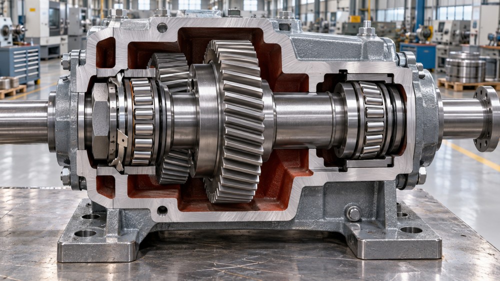
Adapter sleeves are common with tapered-bore spherical roller bearings and similar arrangements because they allow mounting on a plain shaft. Axial movement of the sleeve drives the bearing up the taper, reducing internal clearance and creating the radial grip that holds the inner ring.
This method is effective, but it is sensitive to installation practice. Driving the bearing too far up the sleeve can leave too little operating clearance. Stopping short can allow the assembly to work loose and fret. Measuring the relevant reduction in internal clearance or using the prescribed axial drive-up process is more reliable than judging by nut position alone.
The sleeve, nut, and washer should be inspected as a matched retention system. Damaged sleeve threads, a scored taper, a nut that has bottomed out, or lubricant trapped in the wrong contact area can change the achieved mounting condition. When a tapered-bore bearing has shifted, inspect the shaft surface beneath the sleeve as well. A worn or undersized shaft can prevent the sleeve from maintaining stable grip.
Outer-ring locking needs the same attention
Maintenance work often focuses on the shaft-side components because they are visible after a cover is removed. Yet an outer ring moving in the housing can cause equally serious damage. In a gearbox, the bearing may shift enough to alter gear contact. In a pump, it may affect impeller clearance. In a wheel-end or track assembly, it can change seal position and allow contamination into the lubricant.
Housing shoulders and end covers are commonly used to trap the outer ring between two axial faces. The faces must be clean, flat, and capable of supporting the expected thrust direction. A cover that has been pulled down unevenly by bolts can impose ring distortion. Shims should be clean, undamaged, and retained in the same order used for adjustment. Replacing a damaged end cover with a part that has a different recess depth can change end play even when the bearing part number is correct.
Retaining rings and bolted plates are useful where geometry limits the use of a substantial shoulder. Their suitability depends on the groove or plate having enough strength for the actual axial load. They should not be treated as universal substitutes for a designed thrust face in a high-load application. A retaining ring that repeatedly dislodges may indicate excessive thrust load, incorrect groove dimensions, housing wear, or a bearing arrangement that is no longer aligned with the machine’s operating forces.
Do not confuse axial retention with preload adjustment
Some bearing systems need axial clamping only; others need a controlled preload or end-play setting. The distinction matters most with paired tapered roller bearings, angular contact bearings, and certain wheel, spindle, and gearbox assemblies.
In a simple locating arrangement, the purpose of the locknut is to hold the bearing ring against its shoulder. In an adjustable pair, the same nut, spacer, shim pack, or cover may also determine the internal axial condition of both bearings. A change that seems minor can therefore alter rolling contact, temperature, stiffness, and service life.
Never use preload to hide looseness caused by worn spacers, collapsed shoulders, damaged threads, or a loose housing fit. The assembly may initially feel tight, but the load distribution will be unreliable. Correct the physical location surfaces first, then set preload or end play through the method intended by the machine design.
A practical inspection sequence before reassembly
When a machine has shown bearing creep, abnormal noise, seal damage, or recurring end play, a short structured inspection prevents repeated repairs.
- Record the original arrangement. Note bearing orientation, spacer order, shim position, locking hardware, and the direction of thrust loads. Photographs and simple marks are useful before dismantling.
- Inspect the bearing seat and housing bore. Look for fretting, scoring, discoloration, polishing, corrosion, and evidence that a ring has rotated or walked axially.
- Check locating faces. Clean shaft shoulders, cover recesses, spacers, and bearing abutments. Remove raised metal carefully and replace parts with damaged contact faces.
- Examine the locking components. Replace distorted lock washers, damaged nuts, cracked plates, weak fasteners, worn retaining rings, and sleeves with compromised tapers or threads.
- Confirm the intended fixed and floating positions. This is essential after an earlier repair, housing replacement, or shaft rebuild.
- Mount using the correct force path. Apply installation force only to the ring being fitted. Pressing through the rolling elements can damage the bearing before operation begins.
- Verify final movement. Rotate the assembly by hand where practical, check for smooth motion, and measure the applicable end play, preload condition, or axial location before closing the housing.
Fault patterns that point to a locking problem
Repeated seal failure near a bearing is often an early warning. If the shaft or outer ring shifts, the seal may run off its intended track, lose contact pressure, or be exposed to edge loading. Oil leakage then appears to be a seal issue, while the underlying cause is axial displacement.
Fretting debris is another useful clue. Dark reddish or metallic powder around a shaft seat, sleeve, spacer, or housing bore usually indicates micro-movement. It should prompt inspection of fit, clamping force, and the direction of service loads. Simply cleaning the debris and fitting a new bearing leaves the movement mechanism in place.
Changes in gearbox noise or gear contact can also trace back to bearing location. A shaft that moves axially may change backlash or move a gear away from its designed running position. In this case, replacing gears before confirming the bearing retention stack can create an expensive repeat failure.
Heat should be interpreted carefully. A hot bearing can result from insufficient clearance, excessive preload, lubrication issues, misalignment, contamination, or overload. If locking hardware was recently adjusted, inspect whether the bearing has been over-clamped before assuming lubricant alone is responsible.
Selection should follow the whole assembly, not the hardware catalog
The right bearing locking method comes from the machine drawing and load path. Confirm the bearing type, bore style, shaft geometry, thrust direction, thermal behavior, nearby gears or seals, and whether the arrangement is fixed or floating. Then select or replace the nut, washer, sleeve, cover, plate, or ring as part of that system.
Component traceability and dimensional consistency matter here because small differences in spacer length, sleeve geometry, shoulder depth, or cover recess can change axial position. Industrial power-transmission guidance from platforms such as Global Industrial Machining & Piping Equipment Network (IMPE) is useful when reviewing how bearings, shafts, gearboxes, seals, lubrication, and machined locating surfaces affect one another. The relevant decision is rarely the bearing alone; it is whether the assembled support system preserves its intended position through load, vibration, and temperature changes.
When axial movement has already occurred, treat the bearing as one part of the investigation. Restore the correct location surfaces, use locking hardware designed for the arrangement, preserve any intentional float, and verify the final condition before the machine returns to service. That sequence does more to prevent recurrence than replacing a locknut without finding why the original assembly moved.
Related News
- How to Assess a Rigid Coupling Supplier for Bore Accuracy and Traceable QualityOct 08, 2026Tribology & Kinematics Expert
- Titanium Alloys Compared: Balancing Strength, Corrosion Resistance, and MachinabilityOct 08, 2026CNC Kinematics Architect
- Where Ductile Iron Dismantling Joints Reduce Alignment Risk in Water PipelinesOct 08, 2026Pipeline Metallurgy Scientist
- Selecting a Precision Bearing Sleeve: Fits, Runout, and Material ChoicesOct 08, 2026Tribology & Kinematics Expert
- Face Milling Cutters: How Insert Geometry Affects Finish on Steel and AluminumOct 08, 2026CNC Kinematics Architect
- Single-Acting Cylinders for Clamping: Stroke, Force, and Return Spring ConsiderationsOct 07, 2026Fluid Power Control Strategist