
Bearing Lock Nuts: How to Choose Thread Size, Load Rating, and Locking Method
In a gearbox rebuild, pump assembly, or conveyor drive, a bearing may look perfectly seated until vibration, thermal cycling, or a reversing load begins to move it. The component often responsible for preventing that movement is small and easy to underestimate: the bearing lock nut. Yet an incorrect choice can disturb bearing preload, allow axial creep, damage shaft threads, or make routine maintenance unnecessarily difficult.
Bearing Lock Nuts play a critical role in maintaining bearing position, preload, and operating reliability in shafts, gearboxes, pumps, and other power transmission assemblies. For technical evaluators, selecting the right nut requires more than matching a thread designation. Thread size, bearing arrangement, axial load, locking method, material strength, available mounting space, and installation practice all influence the result.
The most dependable selection process starts by treating the nut, washer or locking feature, shaft thread, bearing, and housing as one assembly—not as separate catalog items. This guide explains how to evaluate that assembly before it reaches the production floor or a field-service site.
Start with the actual job the lock nut must perform
A bearing lock nut is generally used to locate a bearing or related component axially on a shaft, sleeve, or adapter sleeve. In many arrangements, it also establishes or preserves preload, internal clearance adjustment, or the mounting position of a tapered-bore bearing. Its role may seem static, but the forces acting on it are rarely static.
Consider the difference between a lightly loaded electric motor and a quarry conveyor gearbox. The motor may see relatively steady rotation and modest axial forces. The gearbox can face shock loading, torsional vibration, dust contamination, temperature variation, frequent starts, and load reversals. Both may use a threaded locking component, but they should not automatically receive the same locking solution.
Before choosing a part number, define what the nut is expected to resist:
- Axial movement caused by helical gears, thrust loads, or impeller forces
- Loss of bearing preload in angular-contact or tapered roller bearing arrangements
- Loosening caused by vibration, cyclic loading, or shaft acceleration and deceleration
- Movement associated with thermal expansion of the shaft, bearing rings, or adjacent components
- Assembly forces needed to drive a bearing onto a tapered sleeve or tapered shaft seat
This operating view changes the evaluation. A nut that is adequate for simple location may not be suitable for a precision spindle, a high-speed pump, or a reduction gearbox where bearing adjustment directly affects gear contact and noise.
Thread size: match the standard, then verify the geometry
Thread size is the first checkpoint, but it should never be the last. Bearing lock nuts are commonly identified by a nominal thread diameter and pitch, often using metric fine threads. The thread must correspond precisely with the shaft, withdrawal sleeve, or adapter sleeve specified for the bearing arrangement. A similar nominal diameter with a different pitch is not interchangeable.
Technical teams should verify the complete thread callout from the drawing or equipment documentation: nominal diameter, pitch, thread form, tolerance class, thread length, and direction of rotation where relevant. Fine-pitch threads are widely used because they provide more precise axial adjustment and can offer useful resistance to loosening, but they are also more vulnerable to damage from contamination, poor handling, or cross-threading.
The mating length matters as much as the stated diameter. Insufficient thread engagement reduces the ability of the connection to carry axial force safely and can concentrate stress in the first engaged threads. Conversely, a long threaded section does not automatically improve performance if the nut bottoms out on an unintended shoulder, contacts a radius, or prevents the bearing from seating correctly.
Check these physical interfaces during evaluation:
- Thread compatibility: Confirm diameter, pitch, form, and tolerance against the shaft or sleeve drawing.
- Shoulder and fillet clearance: The nut must seat against its intended face without riding on a shaft radius or adjacent component.
- Available axial space: Include the thickness of a lock washer, tab washer, locking plate, or any required removal clearance.
- Tool access: Hook spanner slots, holes, or flats must remain accessible after guards, seals, couplings, and housings are installed.
- Adjacent component position: Verify that the locked assembly does not interfere with seals, labyrinth rings, spacers, or lubrication features.
A useful procurement habit is to request the supplier’s dimensional drawing rather than relying on a generic product image. In industrial maintenance, many fit-up issues emerge from a few millimeters of missing clearance, not from an obvious mismatch in nominal size.
Load rating is not simply the bearing’s load rating
The phrase “load rating” can cause confusion in bearing lock nut selection. A rolling bearing has published dynamic and static load ratings that describe its fatigue and deformation capability. A lock nut must instead be assessed for the axial clamping or retaining force, thread strength, seating-face pressure, and locking security required by the assembly.
Do not assume that a larger bearing automatically means the locking component is sufficiently rated for every application. The relevant forces may arise from mounting preload, applied axial loads, shock events, and the torque used during installation. In a tapered roller bearing pair, for example, tightening may be part of the clearance or preload-setting process. Excessive tightening can overload the bearing; insufficient tightening can leave harmful end play.
Assess axial force in the context of the complete system
For technical evaluation, identify the normal axial load and the credible peak load. Helical and bevel gears generate thrust. Centrifugal pumps may develop hydraulic axial force. Vertical shafts can carry component weight. Hydraulic cylinders, screw drives, and reversing gear trains may impose repeated loads in both directions. If the nut is only intended to retain a bearing against a shoulder, its demand differs from a nut used to actively clamp and adjust a preloaded bearing set.
Also consider load path. The nut may transfer force through a washer, spacer, inner ring, sleeve, or lock plate. Each contact face must be flat enough, strong enough, and correctly supported. A hardened lock washer placed against a soft or damaged spacer can still allow embedment and preload loss over time.
Where high loads, safety consequences, or long maintenance intervals are involved, the selection should be reviewed against the bearing manufacturer’s mounting guidance and the machine designer’s calculated axial loads. The lock nut’s catalog designation alone is not a substitute for this calculation.
Material strength and surface condition deserve attention
Most industrial lock nuts are made from steel, but material grade, heat treatment, coating, and corrosion protection vary by product family and operating environment. In a clean indoor gearbox, standard protected steel may be appropriate. In a water-treatment plant, marine installation, food-processing area, or outdoor mining system, corrosion can compromise threads, locking tabs, and future removability.
Surface treatment should be evaluated as a functional choice, not a cosmetic one. Coatings can influence friction during tightening, while corrosion products can alter torque-tension behavior and make a previously serviceable nut difficult to remove. When stainless steel or corrosion-resistant alternatives are considered, examine compatibility with the shaft material and environment to avoid unintended galling or galvanic corrosion.
Choose the locking method for the failure mode—not for convenience alone
Several locking methods are used with bearing lock nuts. Each has advantages, but each assumes a particular installation condition and risk level.
Tab washer or lock washer systems
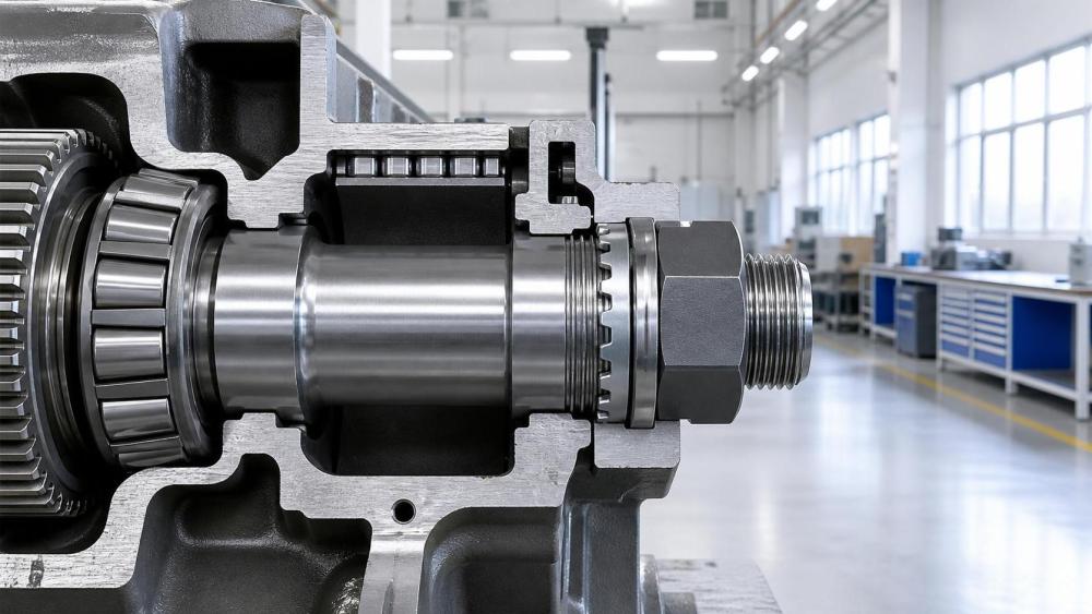
A traditional arrangement uses a lock washer with an inner tab engaged in a shaft keyway or groove and an outer tab bent into one of the nut’s slots. This method is familiar, visually inspectable, and widely used in bearing assemblies. It provides a positive mechanical restraint against rotation of the nut.
Its limitations are practical. The washer must be correctly aligned and bent without cracking. Reusing a distorted tab washer is poor practice, particularly where vibration is present. The shaft needs the correct locating feature, and the installer must have enough access to bend the tab properly. For maintenance teams, this method remains attractive because inspection is straightforward: a tab is either engaged or it is not.
Locking plates, clamp-style devices, and keyed arrangements
Locking plates can provide a robust mechanical solution where severe vibration or load reversal is expected. Depending on the design, a plate may engage a shaft feature and be secured by bolts or tabs. These systems can be more secure than a simple friction-based method, though they require more space and introduce additional components that must be controlled in the bill of materials.
Keyed arrangements are particularly relevant when the shaft geometry and machine design already support positive indexing. They should be assessed carefully for stress concentrations and for the effect of keyways or grooves on shaft fatigue strength.
Set-screw or radial locking designs
Some lock nuts use set screws or radial screws to create a locking action. They can be useful where a tab washer is impractical, but their suitability depends heavily on shaft condition and application duty. A screw point may mark the shaft, create local stress, or complicate future disassembly. In high-precision or frequently serviced equipment, those consequences may outweigh the convenience.
Thread-locking compounds
Adhesive thread lockers can supplement retention in selected applications, especially where minor vibration resistance is needed and future disassembly remains acceptable. They should not be assumed to replace a mechanical lock where the manufacturer specifies one or where high axial loads and repeated thermal cycles are present. Oil-contaminated threads, coating condition, curing temperature, and service temperature all affect adhesive performance.
For critical machinery, a sensible rule is simple: select a locking method that remains credible after the expected vibration, temperature exposure, maintenance cycle, and contamination level have all been considered.
Installation torque is a control variable, not a generic workshop number
Many lock-nut failures begin at assembly. An installer may tighten “until it feels secure,” or apply a torque value copied from an unrelated fastener chart. Neither approach controls bearing setting reliably.
The required tightening method depends on the bearing type and arrangement. Cylindrical-bore bearings located against a shoulder may use a specified tightening procedure. Tapered-bore bearings mounted on sleeves often require measurement of axial drive-up, reduction in radial internal clearance, or another bearing-manufacturer-defined method. Angular-contact bearing sets may need a controlled preload process. The lock nut is part of that procedure; it is not merely a final retaining item.
Use the correct hook spanner, impact tool only where permitted, and calibrated torque equipment where torque is the specified control. Avoid hammering directly on the nut. Apart from damaging slots and threads, impact can introduce uncontrolled preload and mask whether the bearing is properly seated.
After installation, verify the result through the checks relevant to the assembly: bearing clearance or preload, shaft rotation torque, axial end play, locking-tab engagement, runout, temperature during commissioning, and abnormal noise. A short inspection at this stage is usually far less costly than reopening a gearbox after commissioning.
Common selection errors that create avoidable risk
One recurring mistake is selecting by designation alone. A lock nut may fit the thread while being incompatible with the required washer, sleeve, tool, or axial space. Another is treating preload as a tightening target rather than a bearing-system condition. Over-tightening can generate heat and reduce bearing life; under-tightening can permit creep and vibration.
Technical evaluators should also be cautious about mixing components from different systems without checking drawings. A nut, washer, and adapter sleeve may each appear standard, yet their slot patterns, tab locations, widths, or thicknesses may not work together. This is especially relevant when sourcing replacement parts for older equipment or when consolidating suppliers across multiple facilities.
Finally, do not overlook serviceability. A lock nut installed behind a coupling with no spanner access may be acceptable on paper but expensive in the field. For municipal pumping stations, heavy equipment, and remote industrial assets, the ability to inspect, tighten, and replace components safely is part of lifecycle value.
A practical evaluation checklist before release
Before approving Bearing Lock Nuts for procurement or design release, confirm the exact shaft or sleeve thread and mating geometry; identify whether the nut locates, clamps, or adjusts the bearing; establish normal and peak axial loading; select a locking method appropriate to vibration and maintenance conditions; verify material and corrosion resistance; and review the manufacturer’s installation instructions for the specific bearing arrangement.
For OEM and project teams, it is also worth documenting the approved combination of bearing, sleeve, lock nut, washer or plate, and mounting tool. That record reduces substitution risk and gives maintenance personnel a clear reference when equipment is rebuilt years later.
A well-chosen bearing lock nut rarely attracts attention during normal operation—and that is exactly its purpose. By matching thread geometry, load path, locking method, and installation control to the real machine environment, technical teams can protect bearing settings, reduce unplanned intervention, and support more stable performance across power transmission equipment.
Related News
- Using Industrial Air Blow Guns to Clear Chips Without Spreading DebrisOct 15, 2026Fluid Power Control Strategist
- Ductile Iron Pipe Valves: Which AWWA Standards Apply to Water Main Projects?Oct 15, 2026Dr. Elias Vance
- Why Vacuum Suction Cups Lose Grip on MDF in Woodworking MachinesOct 15, 2026CNC Kinematics Architect
- Choosing a Variable Displacement Piston Pump Manufacturer: What to VerifyOct 15, 2026Fluid Power Control Strategist
- Parallel vs. Angular Pneumatic Grippers for Confined Assembly StationsOct 15, 2026Fluid Power Control Strategist
- Die Castings vs. Investment Castings: Which Costs Less at Your Production Volume?Oct 14, 2026Foundry Phase-Change Fellow