
Why Linear Guide Rails Fail Early on CNC Machines—and How to Prevent It
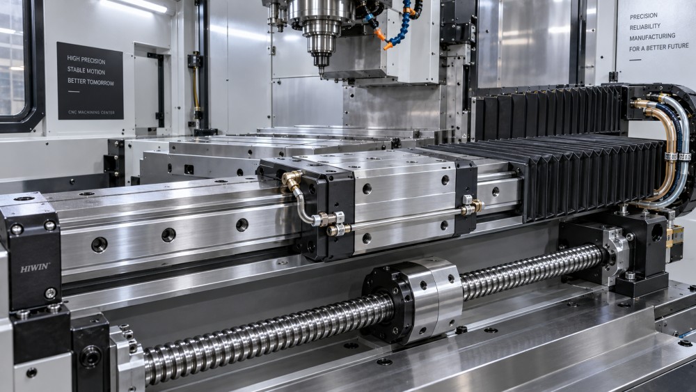
Early failure of linear guide rails is rarely caused by the rail alone. In CNC machines, premature wear usually develops because the rail, carriage block, mounting surfaces, lubrication system, seals, and machine geometry are no longer functioning as one controlled system. Replacing a damaged block without finding that system-level cause often restores motion briefly, then repeats the same failure.
The practical consequence is broader than a noisy axis. Deteriorating linear guide rails for CNC machines can introduce positioning variation, increased servo load, chatter, poor surface finish, inconsistent tool life, and, in severe cases, axis seizure. The useful maintenance question is not simply whether a guide rail is worn, but what loading or contamination mechanism produced the wear pattern.
Failure usually begins with a mismatch between load path and guide capacity
Linear guides are designed to carry loads in specified directions while maintaining low-friction motion. On a CNC axis, however, their real load is affected by cutting force, moving mass, acceleration, tool overhang, spindle orientation, fixture position, cable carrier drag, ballscrew alignment, and the stiffness of the machine structure. A guide may be correctly sized on paper but still experience damaging local load if the carriage blocks are not sharing force as intended.
One common example is uneven loading between multiple blocks on the same axis. A gantry beam, saddle, or table may have four blocks, but small differences in mounting height, rail parallelism, or assembly sequence can leave one or two blocks carrying a disproportionate share of the moment load. The overloaded block develops raceway indentation or accelerated rolling-element fatigue while the other blocks appear comparatively normal.
Overloading is not limited to heavy workpieces. Aggressive acceleration and deceleration can create high inertial forces, especially where a heavy table moves rapidly over a short stroke. Interrupted cutting, milling with excessive radial engagement, crashes, and repeated hard-limit impacts can impose shock loads far above normal operating conditions. The resulting damage may not be immediately visible, but it can later appear as a recurring rough spot, rising motor current, or vibration at a repeatable axis position.
Before classifying a rail as overloaded, distinguish between constant load and moment load. A carriage system can tolerate a substantial vertical load yet fail early under pitching, yawing, or rolling moments caused by an off-center workpiece, an extended fixture, or cutting forces acting far from the guide centerline. This distinction matters because adding lubricant or fitting a higher-capacity block will not correct a structural moment problem.
Lubrication failure is often a delivery problem, not simply an empty reservoir
Guide blocks need a stable lubricant film between rolling elements and raceways. Without it, metal-to-metal contact increases, friction rises, and the polished raceway surface begins to degrade. Early symptoms can include darkened or discolored grease, increasing running resistance, fine metallic debris, and a progressive change in axis sound.
It is easy to check whether the central lubrication reservoir contains oil or grease. It is harder, and more important, to confirm that lubricant reaches every block in the required amount. Metering units can clog, distribution lines can crack or become pinched, fittings can loosen, and a blocked line can leave one carriage dry while the rest of the machine appears adequately lubricated.
Lubricant selection also matters. Oil and grease systems are not interchangeable merely because both reduce friction. The specified lubricant viscosity, base oil type, additives, and consistency are selected for speed, load, temperature, and the machine’s distribution method. Mixing incompatible greases can alter consistency, reduce oil separation behavior, or obstruct narrow passages. Introducing a heavier grease to “make it last longer” can be especially harmful in a system designed for oil or a low-consistency grease.
Over-lubrication is not a harmless precaution. Excess grease can retain chips and abrasive dust near seals, increase churning resistance at high speed, and make it difficult to identify fresh leakage or contamination. The aim is controlled delivery, not maximum quantity.
A useful inspection sequence is to operate the lubrication cycle, verify outlet flow or metering action at the relevant points, inspect all visible lines and fittings, and then compare the condition of blocks across the axis. A dry or noisy block located downstream of a functioning pump points to a distribution fault, while widespread dry running suggests an incorrect interval, depleted supply, unsuitable lubricant, or a broader system failure.
Contamination leaves clues that distinguish it from normal fatigue
Contamination is among the most destructive causes of early rail damage because rolling elements repeatedly press foreign particles into the raceway under high contact stress. Coolant residue, abrasive grinding dust, cast iron fines, aluminum chips, hardened swarf, dried grease, and airborne shop dust can all enter a guide system when seals, bellows, covers, wipers, or chip-management arrangements are compromised.
Damage caused by contamination often has a different character from fatigue caused by normal service loading. Instead of smooth, progressive surface deterioration, maintenance teams may find scoring, dents, scratches, embedded particles, rough or gritty motion, and localized clicking. Chips found in old lubricant are not proof of the origin of the problem, but they are a strong reason to inspect sealing and enclosure paths before installing replacement parts.
Coolant deserves particular attention. A poorly directed coolant stream can wash lubricant from exposed rail sections or carry fine particles toward the carriage end seals. Water-based coolant that dries on unprotected surfaces may leave residues that attract moisture or trap debris. On machines producing abrasive materials or fine particulate chips, standard contact seals may not provide enough protection without functioning telescopic covers, scraper arrangements, or suitable positive-air protection in the surrounding enclosure design.
Cleaning practices can create the same risk they are intended to remove. Compressed air directed along an exposed rail can force chips past the wiper rather than remove them safely. Wiping a rail with contaminated cloths can drag abrasives over the raceway. During service, clean lint-free materials, controlled solvent use compatible with seals and lubricant, and protection of open blocks are more reliable than aggressive blow-off methods.
Misalignment is a hidden source of preload, heat, and uneven wear
A linear guide system requires rail mounting surfaces that are sufficiently flat, straight, clean, and rigid for the manufacturer’s stated installation limits. When a rail is tightened onto a distorted, burred, painted, corroded, or damaged mounting face, the rail can be forced into a shape that creates internal stress. The carriage may still move, but it is no longer running freely.
Parallelism between paired rails is equally important. If two rails are installed with excessive deviation, the blocks are compelled to compensate as the axis travels. That condition can increase preload at certain positions and cause running resistance to vary across the stroke. It is frequently mistaken for ballscrew trouble because servo load rises as the axis moves through the affected area.
Thermal behavior can complicate diagnosis. A machine may move smoothly when cold and become tight after extended operation, or the reverse may occur after the structure stabilizes. Temperature-related changes do not automatically mean the rails are defective. They can indicate excessive preload, insufficient clearance in the mounting arrangement, poor alignment between rails and ballscrew supports, or a structural distortion caused by heat from cutting, coolant, motors, or a nearby spindle assembly.
Installation damage is another concern. A rail dropped onto a mounting surface, tightened unevenly, or located against a damaged reference shoulder can be permanently compromised. Burrs around bolt holes are particularly harmful because they can lift the rail locally while remaining hard to see. Mounting bolts tightened in an unsuitable sequence can also pull the rail out of its intended line.
When replacing rails, do not assume the existing base surface remains acceptable because the prior assembly operated for some time. Measure and inspect the mounting face, reference edges, bolt-hole condition, rail seating, parallelism, and carriage running resistance. A replacement rail installed onto the same defective interface will inherit the same failure mechanism.
Preload and interchangeability errors can shorten life before production begins
Guide blocks are available with different preload classes and accuracy grades. Higher preload can improve rigidity and reduce displacement under load, but it also raises friction, heat generation, and sensitivity to alignment error. A preload choice suitable for a rigid precision machining center may be unsuitable for a machine frame with lower stiffness, longer travel, or less controlled mounting geometry.
A common service error is to treat rails and blocks of similar dimensions as interchangeable. Nominal size, bolt pattern, and external dimensions are not enough. Differences in rail profile, ball circulation design, preload, accuracy class, seal configuration, lubrication port arrangement, and load rating can affect fit and performance. Mixing components from different series, or fitting a replacement block to an existing rail without confirming compatibility, can create unpredictable contact conditions.
Even within a compatible product family, replacement strategy should reflect the damage mechanism. If a block has failed from contamination or lubrication starvation, the rail surface may already be damaged. Fitting a new block onto a scored or indented rail can rapidly damage the replacement. Conversely, replacing rails without correcting a failed lubrication manifold or worn bellows simply introduces new components into the same hostile environment.
Symptoms should be mapped to axis position before parts are removed
Premature guide failure is easier to isolate when symptoms are recorded against machine position, operating temperature, axis direction, and load condition. A complaint such as “the axis is noisy” is too broad to guide a reliable repair. Noise that occurs at one repeatable position suggests a localized rail defect, contamination zone, damaged cover section, or structural distortion. Noise present throughout the travel may point toward general lubrication failure, incorrect preload, ballscrew damage, or a drive-related issue.
Axis motor current trends, if available from the CNC control or drive system, can be useful supporting evidence. A gradual increase in current required to maintain the same feed rate may indicate growing mechanical resistance. It should not be treated as proof of rail failure on its own, because ballscrews, bearings, way covers, cable carriers, gearbox elements, and servo tuning can also affect the reading.
Before disassembly, isolate the machine safely and inspect external contributors: way covers, cable carriers, lubrication lines, ballscrew guards, chip accumulation, coolant nozzles, and evidence of crashes or fixture interference. This avoids the costly mistake of replacing guides while an external component continues to impose drag or introduce contamination.
Installation discipline determines whether a repair becomes a lasting correction
Replacement work should begin with a documented baseline: backlash or positioning behavior where relevant, axis current, observed noise location, lubricant condition, rail and block identification, and the state of covers and lubrication hardware. This record provides a reference after reassembly and makes repeated faults easier to trace.
Mounting surfaces need to be cleaned without scratching them, then checked for burrs, raised dents, corrosion, and fretting marks. Reference shoulders must be intact. If the machine manufacturer specifies a rail alignment method, bolt-tightening sequence, torque, lubricant, or calibration procedure, that instruction takes precedence over generic practice. Guide suppliers also provide installation limits and handling guidance for their own rail series; these details are essential when preload or accuracy requirements are tight.
During assembly, avoid forcing the carriage over unprotected rail ends or allowing it to lose rolling elements. Keep parts identified by axis and location where matched sets are involved. Confirm that lubrication reaches the blocks before extended travel. After installation, move the axis slowly through its full stroke, monitor for abnormal resistance, and inspect for interference from covers and cable carriers before returning to production speeds.
The most effective prevention program is therefore not a calendar-only lubrication task. It combines verified lubricant delivery, contamination control, inspection of covers and wipers, monitoring of motion resistance, prompt investigation after crashes, and careful geometric checks whenever rails, ballscrews, machine structures, or major axis components are disturbed. Linear guides can provide long service life, but only when the machine preserves the alignment, cleanliness, and load distribution on which that life depends.
Related News
- How to Assess a Rigid Coupling Supplier for Bore Accuracy and Traceable QualityOct 08, 2026Tribology & Kinematics Expert
- Titanium Alloys Compared: Balancing Strength, Corrosion Resistance, and MachinabilityOct 08, 2026CNC Kinematics Architect
- Where Ductile Iron Dismantling Joints Reduce Alignment Risk in Water PipelinesOct 08, 2026Pipeline Metallurgy Scientist
- Selecting a Precision Bearing Sleeve: Fits, Runout, and Material ChoicesOct 08, 2026Tribology & Kinematics Expert
- Face Milling Cutters: How Insert Geometry Affects Finish on Steel and AluminumOct 08, 2026CNC Kinematics Architect
- Single-Acting Cylinders for Clamping: Stroke, Force, and Return Spring ConsiderationsOct 07, 2026Fluid Power Control Strategist