
Which Torque-Transmitting Shaft Coupling Fits Misalignment and Shock Loads?
When a drive train runs smoothly on a test stand but fails after installation, the coupling is often where the real story begins. The motor may be correctly sized, the gearbox may meet its rating, and the driven machine may be sound—yet shaft offset, torsional vibration, or an abrupt load reversal can turn a seemingly minor connection into a recurring maintenance problem.
For technical evaluators, selecting torque transmitting shaft couplings for misalignment and shock loads is not simply a matter of choosing the highest torque value in a catalog. The better question is: which coupling can transmit required torque while protecting the connected shafts, bearings, seals, and gearbox from the actual movement and load behavior of the machine?
In most demanding industrial applications, elastomeric flexible couplings are the first choice when meaningful shock absorption and vibration damping are needed. Grid couplings and certain high-flex gear couplings are often better suited to high-torque, heavy-duty drives where operating conditions are harsh but shock capacity and misalignment tolerance must coexist. Disc, diaphragm, and bellows couplings offer excellent precision and torsional rigidity, but they are generally less forgiving of severe shock loads.
Start with the load event, not the nominal torque
A coupling rated for continuous torque can still be a poor fit for a crusher feeder, reciprocating pump, bucket elevator, mixer, rolling line, or conveyor that starts under load. Nominal torque describes the expected steady operating condition. It does not fully describe what happens during a jam, an emergency stop, a motor reversal, a fluctuating process load, or a high-inertia startup.
Shock loading creates short-duration torque peaks that can overstress hubs, keys, bolts, flexible elements, and shaft interfaces. At the same time, misalignment creates repeated cyclic forces. Together, these conditions are particularly damaging: the coupling is asked to flex continuously while transferring sudden torque pulses.
Before comparing coupling types, the evaluation team should document the conditions that shape selection:
- Continuous torque, peak torque, and startup or stall torque
- Driver and driven equipment, including motor, gearbox, pump, fan, mill, or conveyor details
- Rotational speed range and the number of starts, stops, reversals, and load cycles
- Angular, parallel, and axial misalignment expected after installation and during operation
- Rotational inertia, especially for large fans, drums, flywheels, and long conveyors
- Torsional vibration risk, including pulsating loads from piston pumps, compressors, and engines
- Ambient temperature, moisture, dust, corrosive exposure, washdown requirements, and access for maintenance
One important distinction is often missed: installation alignment is not the same as operating alignment. Thermal growth, baseplate distortion, pipe strain, settlement, and bearing wear can all change shaft position after commissioning. A coupling should accommodate the expected operating condition with margin; it should not be selected on the assumption that laser alignment will remain perfect indefinitely.
Which coupling designs handle misalignment and shock best?
There is no universal “best” coupling, because torsional stiffness, damping, backlash, speed capability, and maintenance needs pull the decision in different directions. The following comparison is a practical starting point for industrial drive assessment.
Elastomeric couplings: usually the most forgiving answer
For a drive that experiences frequent starts, moderate shock, vibration, and ordinary shaft movement, elastomeric couplings are commonly the most balanced option. Their rubber or engineered polymer elements deform under load, allowing the coupling to absorb torsional peaks rather than pass every impact directly into the gearbox and bearings.
Tyre couplings, elastomeric sleeve couplings, jaw couplings, and similar designs vary greatly in stiffness and capacity. A soft element may reduce transmitted vibration effectively but can permit more torsional wind-up. A stiffer element improves motion control and torque response but transmits more shock. This is why “flexible” alone is not a sufficient specification.
They are especially useful where equipment protection matters as much as torque transfer: pump drives subject to hydraulic transients, conveyor systems with uneven material loading, fans with intermittent process resistance, or machinery installed on structures that experience minor movement. In many cases, the replaceable element also provides a practical maintenance advantage because it can be changed without moving the connected machines.
However, elastomer properties change with heat, oil exposure, ozone, UV exposure, and chemical contact. Technical evaluators should verify the permitted temperature range and fluid compatibility rather than assuming all elastomer elements behave alike. Repeated overload can also tear or permanently deform the flexible element, so a coupling should never be used as a substitute for proper torque limiting where destructive jams are possible.
Grid couplings: a strong candidate for rugged, shock-prone machinery
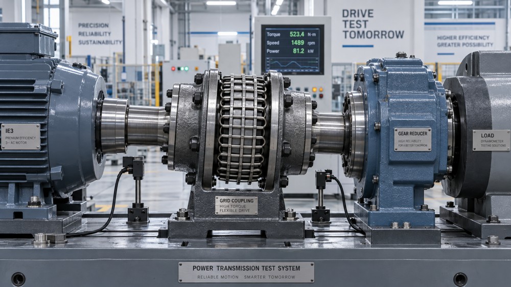
A grid coupling uses a serpentine spring element fitted between grooved hubs. Its mechanical flexibility allows it to accommodate shaft misalignment while cushioning torsional impacts more effectively than many all-metal designs. For equipment such as heavy-duty conveyors, mills, mixers, crushers, reciprocating machinery, and industrial pumps, grid couplings remain a proven choice where substantial torque and shock capacity are required.
The grid spring spreads load across multiple contact areas and can soften sudden torque changes. It does not provide the same damping character as a rubber element, but it often offers a useful middle ground: more robust torque transmission than lighter elastomeric designs, with more resilience under shock than rigid or thin metallic couplings.
The trade-off is maintenance. Traditional lubricated grid couplings need suitable grease, intact seals, and inspections for spring wear, hub groove wear, and lubricant condition. In dusty mining, cement, steel, and aggregate environments, neglected lubrication can quickly turn an otherwise appropriate coupling into a source of backlash, heat, and vibration. If access is difficult, include serviceability in the selection decision from the beginning.
Gear couplings: high torque capacity, but not a shock absorber
Gear couplings are valued in steel production, marine drives, power generation, rolling equipment, and other high-torque applications because crowned gear teeth can accommodate angular misalignment while transmitting very large loads in a compact envelope. With suitable hub geometry, they may also manage certain parallel and axial movements.
They are not, however, inherently good vibration dampers. A gear coupling transmits torque through metallic tooth contact, which means load reversals and shock events can travel through the drive system with relatively little cushioning. When the application involves severe impact loading, an engineering review may favor a resilient coupling, a torsional damping element, or a separate torque-limiting device ahead of or alongside the gear coupling.
Lubrication is central to gear coupling performance. Inadequate lubricant, failed seals, excessive misalignment, or poor assembly can cause tooth wear and generate high reaction forces. Selecting a larger gear coupling without resolving alignment or torsional issues may postpone failure rather than eliminate it.
Misalignment has three directions—and each affects the choice
Technical specifications sometimes list a single “misalignment allowance,” but actual shaft movement is more complex. Angular misalignment occurs when shaft centerlines meet at an angle. Parallel or radial offset occurs when shafts remain parallel but their centerlines are displaced. Axial movement is end float along the shaft axis, often caused by thermal expansion or process forces.
A coupling that tolerates angular misalignment well may have lower capacity for parallel offset. Likewise, a design that accepts axial movement may not be suited to frequent high-speed operation. The evaluator should request separate limits for all three directions and verify whether stated values can occur simultaneously. Catalog limits are often maximum values, not recommended continuous operating conditions.
Excessive reliance on coupling flexibility is a common error. A flexible coupling is designed to accommodate residual and dynamic movement, not to compensate for an improperly installed drive. Persistent misalignment increases bearing loads, raises coupling temperature, accelerates element wear, and may produce vibration that is mistaken for an unbalanced rotor or damaged gearbox.
Do not ignore torsional stiffness and backlash
Shock tolerance does not automatically mean good motion control. In positioning systems, test rigs, robotics, machine tools, and precision indexing equipment, torsional deflection and backlash can affect accuracy. Disc and bellows couplings are often selected because they offer high torsional rigidity and nearly backlash-free torque transmission. Yet their low damping means they may transfer shock more directly into sensitive drivetrain components.
For heavy machinery, a modest degree of torsional compliance can be beneficial. It smooths impact energy and can reduce peak stresses. For a servo-driven axis, the same compliance may create lag, oscillation, or unstable control behavior. The coupling therefore needs to be evaluated as part of the entire mechanical system, not as an isolated commodity part.
Where repeated load reversal is expected, ask whether the coupling has measurable backlash under operating torque and how wear changes that condition over time. This question is particularly important for geared couplings and mechanical assemblies with clearances. A coupling that is quiet when new may behave differently after months of cyclic duty.
A practical selection path for procurement and engineering review
A disciplined review can avoid both under-sizing and unnecessary over-specification. Begin by establishing the service factor from the actual duty cycle, not from a generic description such as “industrial use.” A continuously operating clean-room pump and a reversing slag conveyor should not receive the same interpretation of service severity.
- Define transmitted torque. Calculate running torque from power and speed, then identify startup, acceleration, reversal, jam, and emergency-stop torque events.
- Map shaft movement. Record alignment readings, anticipated thermal growth, structural movement, and allowable axial float from the driven equipment manufacturer.
- Choose the needed behavior. Prioritize damping for shock-prone systems; prioritize torsional stiffness and low backlash for precision systems; prioritize high torque density for compact heavy drives.
- Check speed and balance requirements. High-speed couplings require attention to balance quality, centrifugal effects, and guard design.
- Review bore, keyway, shrink-fit, and hub connection details. The shaft-to-hub interface must safely transmit torque without creating excessive stress concentration.
- Assess maintainability. Consider whether lubrication, element replacement, inspection, and alignment checks can realistically be completed in the installed location.
For global sourcing teams, technical documentation should include dimensional drawings, material information, torque and speed ratings, misalignment limits by direction, allowable ambient conditions, lubrication instructions where applicable, and installation requirements. On custom-machined hubs or special forged shafts, dimensional tolerances, keyway standards, runout, heat treatment, and traceability should be reviewed alongside the coupling selection.
The decision in plain terms
If the drive must tolerate misalignment, vibration, and recurring moderate shock loads, an appropriately sized elastomeric flexible coupling is often the preferred starting point. If torque is high and the application is rugged—such as conveying, crushing, mixing, or heavy process equipment—a grid coupling is frequently a stronger alternative, provided its lubrication and inspection needs are acceptable.
For very high-torque machinery where misalignment accommodation is essential, gear couplings remain important, but they should be paired with realistic alignment control and, where needed, separate measures for shock mitigation. Disc and diaphragm couplings are excellent when precision, speed, and maintenance-free metallic construction outweigh the need for damping.
The right torque-transmitting shaft coupling does more than connect two shafts. It manages the imperfect reality between them: movement, impact, heat, vibration, and the gradual changes that occur over years of service. Evaluating that reality early helps protect the full power transmission assembly—and makes the coupling a reliable part of uptime rather than the next unexpected shutdown.
Related News
- How to Assess a Rigid Coupling Supplier for Bore Accuracy and Traceable QualityOct 08, 2026Tribology & Kinematics Expert
- Titanium Alloys Compared: Balancing Strength, Corrosion Resistance, and MachinabilityOct 08, 2026CNC Kinematics Architect
- Where Ductile Iron Dismantling Joints Reduce Alignment Risk in Water PipelinesOct 08, 2026Pipeline Metallurgy Scientist
- Selecting a Precision Bearing Sleeve: Fits, Runout, and Material ChoicesOct 08, 2026Tribology & Kinematics Expert
- Face Milling Cutters: How Insert Geometry Affects Finish on Steel and AluminumOct 08, 2026CNC Kinematics Architect
- Single-Acting Cylinders for Clamping: Stroke, Force, and Return Spring ConsiderationsOct 07, 2026Fluid Power Control Strategist