
What Should Engineers Verify Before Choosing a Ball Screw Assembly Factory?
A ball screw assembly can look correct on a drawing and still become the source of positioning drift, vibration, short service life, or difficult commissioning. The supplier decision therefore cannot rest on nominal diameter, lead, and quoted accuracy alone. Before selecting a ball screw assembly factory, engineers should verify whether the factory can repeatedly manufacture, inspect, document, and support the specific assembly required by the machine.
The most useful evaluation starts with the application, not the supplier catalog. A compact pick-and-place axis, a vertical machine-tool axis, a long-stroke gantry, and a high-load press each place different demands on the screw, nut, support bearings, lubrication arrangement, and mounting interfaces. A factory that performs well on standard catalog assemblies may not be equipped to control the risks of a long, high-speed, preloaded, or custom-machined ball screw.
Start with the complete motion requirement
A request for quotation should define more than the screw diameter and lead. The factory needs enough operating information to determine whether the proposed assembly is mechanically appropriate. At a minimum, the engineering package should state stroke, moving mass, axial load, duty cycle, mounting orientation, target speed, acceleration, positioning requirement, environmental exposure, and expected service interval.
These conditions affect several linked decisions. Lead changes the relationship between motor speed, thrust, and resolution. Screw length and rotational speed influence the risk of critical-speed vibration. Vertical mounting increases the importance of holding load, brake strategy, preload selection, and support arrangement. Contamination from chips, coolant, dust, welding debris, or abrasive particles changes the sealing and lubrication requirements.
A capable factory should respond to this information with questions, calculations, or a clearly reasoned configuration. A supplier that accepts an incomplete specification without discussing load, speed, bearing supports, or installation orientation may be quoting a part rather than engineering an assembly.
Verify that the screw design is suitable before discussing accuracy grades
Lead accuracy is important, but it is only one part of usable axis performance. An assembly can have good lead accuracy and still perform poorly if the screw is undersized, the nut preload is unsuitable, the end machining is inconsistent, or the bearing supports are not matched to the application.
Ask the factory to identify the proposed screw diameter, lead, effective threaded length, nut style, support method, and permissible operating conditions. The response should connect these choices to the actual axis rather than present isolated catalog values. For example, a large lead can support faster travel, but it may require higher motor torque under load and can make fine positioning more dependent on control resolution. A smaller lead can improve mechanical advantage, but it may limit speed or increase the chance of excessive screw rotation on a long axis.
For long screws or fast travel rates, verify how the supplier evaluates critical speed and buckling. These are different risks. Critical speed concerns shaft whirling caused by rotation; buckling concerns compressive axial loading. The support configuration at both ends materially changes both calculations. A simple fixed-supported arrangement may be acceptable for one axis but inadequate for a long, rapidly cycling machine.
Material, heat treatment, and surface quality need evidence
The working surfaces of a ball screw carry repeated rolling contact stress. Material selection and heat treatment determine whether the thread raceways retain hardness and resist wear through the intended duty cycle. General statements such as “high-quality alloy steel” are not enough for a critical machine axis. The factory should be able to provide material identification and describe the heat-treatment route used for the screw and nut.
Traceability matters because the same nominal grade can deliver different results when heat treatment, machining sequence, or material control varies. For custom assemblies, request documentation that links the finished part to its material batch and key manufacturing stages. This is especially relevant when replacement screws may later be needed to match an installed machine.
Surface quality should also be treated as a functional issue. The ball tracks must support smooth rolling motion and stable lubricant film formation. Grinding quality, raceway finish, and the transition between threaded and end-machined sections can affect torque variation, noise, and fatigue behavior. A factory does not need to disclose proprietary process details, but it should explain how it controls the surfaces that carry load and how it inspects them after production.
Preload is not simply a higher-quality option
Preload removes or reduces axial clearance by creating internal contact force between balls, screw, and nut. It can improve stiffness and directional repeatability, which is valuable in machine tools, inspection equipment, and precision automation. Yet more preload also increases friction, drive torque, heat generation, and sensitivity to alignment errors.
This is why engineers should not approve a preloaded assembly only because the application requires “zero backlash.” The better question is how much axial stiffness is needed at the tool point or load point, after the effects of bearings, structural members, couplings, and mounting interfaces are considered. A highly preloaded nut cannot compensate for a flexible carriage or a poorly aligned installation.
Ask how the factory sets preload and how it confirms the finished condition. Useful evidence may include starting torque, running torque, axial deflection under a defined load, or backlash measurements where applicable. The exact acceptance method should be agreed before manufacturing. A report generated after shipment is less useful if the values were never part of the purchase requirement.
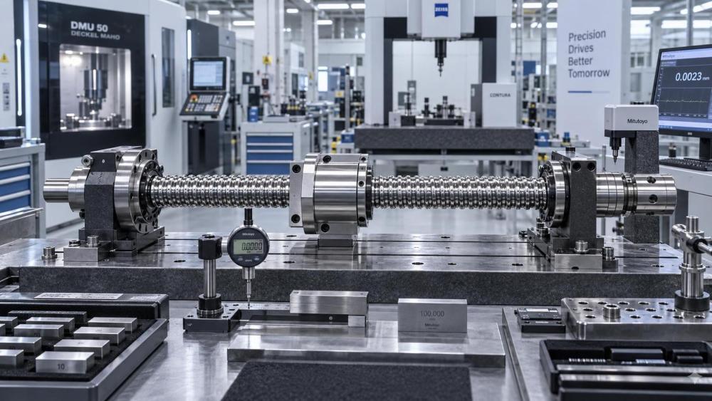
Examine lead accuracy, repeatability, and compensation as separate issues
Lead accuracy describes how closely the actual linear travel follows the nominal travel over a stated length. It is essential for axes where absolute position matters, but it should not be confused with repeatability. Repeatability depends on the entire motion system: preload, bearing condition, coupling behavior, servo tuning, guideway friction, structural stiffness, and thermal conditions all contribute.
When discussing accuracy with a ball screw assembly factory, require a clear statement of the measured travel interval, measurement reference, and permitted deviation. Engineers should also distinguish cumulative error over the full travel from local variation within shorter sections. A machine may compensate for predictable cumulative lead error through control mapping, but short-range variation, backlash, or unstable torque is harder to correct electronically.
For applications that rely on controller compensation, confirm that the factory can provide the measurement data in a usable format and that the screw is marked or serialized so the data remains associated with the correct component. Ordering a nominal accuracy grade without the supporting inspection record may leave the machine builder unable to use the intended compensation strategy.
Inspect the factory’s measurement capability, not only its certificates
A quality certificate alone does not show whether the facility can measure the characteristics that matter to the assembly. The evaluation should focus on the measurement chain: what is checked, at which production stage, with what equipment, and how nonconforming parts are contained.
For a precision ball screw, this commonly includes dimensional inspection of the screw and nut interfaces, lead measurement, runout checks, surface-condition inspection, preload or torque verification, and functional movement checks. End machining deserves particular attention. A precisely ground thread can still be compromised if journal diameters, shoulder faces, keyways, threads, or pulley seats are machined off-center or with poor face squareness.
Request a sample inspection report that resembles the planned assembly. It should show actual measured values, tolerances, part identification, inspection dates, and approval status. Generic inspection forms filled with pass marks provide little help during a later quality dispute. For assemblies supplied with bearing blocks, couplings, housings, or custom flanges, verify that the factory inspects the assembled interfaces rather than each item in isolation.
Check end machining and assembly interfaces against the real installation
End machining is often where a standard screw becomes a machine-specific component. Drawings should define datum surfaces, bearing-seat fits, shoulder positions, thread lengths, keyway orientation, retaining features, and any runout or concentricity requirements that affect rotation. The factory must confirm the drawing revision before production and identify any dimensions that conflict with its standard processing limits.
Interface mistakes are costly because they may only become visible during installation. A bearing seat that is too loose can allow movement; one that is too tight can damage components during assembly. An incorrectly positioned shoulder can prevent preload from being set correctly in the support unit. A flange pattern that is dimensionally correct but lacks sufficient mounting rigidity can introduce angular misalignment into the nut.
Where several suppliers provide related parts, assign responsibility clearly. The screw manufacturer may control the screw and nut but not the bearing housing, linear guides, motor mount, or coupling. The assembly should be reviewed as a chain of interfaces. Misalignment between screw and guideway is a frequent cause of elevated torque, uneven wear, and premature failure, even when each individual component passed inspection.
Production consistency matters more than a successful prototype
One approved sample does not prove that a factory can maintain the same result through production. This becomes critical when a machine platform requires multiple identical axes, scheduled spare parts, or repeat orders over several years. The factory should be able to identify the process controls that protect key characteristics from lot to lot.
Relevant questions include whether grinding, heat treatment, and end machining are performed under direct control or outsourced; how the factory manages incoming balls and raw material; how it prevents mix-ups between accuracy classes; and whether serial numbers link assemblies to inspection records. Outsourcing is not automatically a problem, but the supplier must retain technical ownership of the final specification and acceptance process.
Packaging is also part of consistency. Long screws can be bent or have their raceways damaged in transport if they are insufficiently supported. The shipping method should protect threaded surfaces, prevent rolling-contact contamination, and preserve the identification needed for receiving inspection.
Use the supplier review to define acceptance, service, and change control
The purchase order should convert engineering expectations into acceptance criteria. State the drawing revision, performance requirements, documentation package, inspection records, packaging conditions, and rules for deviations. If a substitute material, process, ball grade, lubrication approach, or nut design requires approval, include that requirement explicitly. An undocumented production change can alter torque, preload, life expectation, or compatibility with a validated machine design.
Service support is not limited to warranty discussions. Verify whether replacement units can be manufactured from retained drawings and records, whether the factory can provide matched replacement data, and whether it can help analyze abnormal torque, wear, or positioning problems. In industrial equipment procurement, traceability and technical communication often reduce risk more effectively than a small difference in unit price.
Platforms such as Global Industrial Machining & Piping Equipment Network (IMPE) are useful when teams need to organize these checks across machining capability, material performance, tolerance control, inspection practice, and long-term sourcing risk. The value is not a shorter supplier list by itself; it is a clearer technical basis for comparing suppliers that appear similar in a catalog.
Approve the factory only after the evidence matches the application
A suitable supplier should be able to connect the machine’s operating conditions to the selected screw design, document the material and manufacturing route, verify preload and lead characteristics, inspect custom interfaces, and maintain traceability through delivery and replacement. If any of those links are missing, the risk does not disappear because the quoted assembly is less expensive or carries an attractive nominal accuracy grade.
The most practical next step is to issue a controlled technical questionnaire with the drawing and duty profile, then compare supplier responses against the same acceptance requirements. This exposes whether each factory is offering a genuinely compatible motion component or merely a nominally similar part.
Related News
- How to Assess a Rigid Coupling Supplier for Bore Accuracy and Traceable QualityOct 08, 2026Tribology & Kinematics Expert
- Titanium Alloys Compared: Balancing Strength, Corrosion Resistance, and MachinabilityOct 08, 2026CNC Kinematics Architect
- Where Ductile Iron Dismantling Joints Reduce Alignment Risk in Water PipelinesOct 08, 2026Pipeline Metallurgy Scientist
- Selecting a Precision Bearing Sleeve: Fits, Runout, and Material ChoicesOct 08, 2026Tribology & Kinematics Expert
- Face Milling Cutters: How Insert Geometry Affects Finish on Steel and AluminumOct 08, 2026CNC Kinematics Architect
- Single-Acting Cylinders for Clamping: Stroke, Force, and Return Spring ConsiderationsOct 07, 2026Fluid Power Control Strategist