
Universal Joints in Drive Systems: How to Prevent Misalignment and Premature Wear
A driveline can look acceptable while standing still and still destroy a universal joint once the machine is under load. The usual pattern is a growing vibration at a particular speed, warm bearing cups, rust-colored dust around seals, repeated loss of grease, or a joint that develops looseness far earlier than expected. In service work, replacing the joint alone often restores operation only briefly because the underlying shaft angle, mounting position, yoke phasing, or support condition has not been corrected.
The practical answer is to treat premature universal joint wear as an alignment problem until inspection proves otherwise. A single universal joint does not transmit constant rotational speed when it operates at an angle. A properly arranged driveline controls that speed variation by using compatible joint angles and correctly phased yokes. When those conditions change because of sagging mounts, an altered ride height, a bent shaft, worn splines, or an incorrect replacement part, the joint bearings are forced to carry vibration and cyclic loads they were not intended to absorb.
Start with the symptoms, but do not diagnose by vibration alone
Drive-system vibration can come from several sources: imbalance, damaged tires or pulleys, gearbox defects, loose supports, bent shafts, or a failing Universal Joint. The service history and the direction of the vibration help narrow the cause. A vibration that appears after a shaft, transmission, axle, pump, or equipment mount has been replaced should immediately raise concern about driveline geometry. A vibration that increases with road or shaft speed but remains present even when torque direction changes may indicate shaft runout or imbalance. A clunk during engagement, reversing, or load transfer more often points to joint clearance, spline wear, flange looseness, or excessive backlash elsewhere in the drive.
Do not assume that a joint with no obvious radial play is healthy. Needle bearings can brinell or corrode before free play becomes easy to feel by hand. A cup may also be seized in its yoke bore, causing the cross to articulate on only part of its bearing surface. That condition can create heat, stiffness, and seal damage long before the joint becomes visibly loose.
- Inspect for polished bearing-cap surfaces, displaced clips, cracked seal lips, missing grease fittings, and orange or dark powder near the cups.
- Look for a shiny witness mark where the shaft, yoke, or flange may be contacting a guard, frame member, exhaust section, hose, or adjacent component.
- Check whether the vibration began after suspension work, driveline removal, a gearbox swap, a lift or lowering modification, or replacement of a center support bearing.
- Record the operating condition: speed, load direction, articulation position, and whether the problem occurs only when the machine is loaded.
A joint that fails repeatedly in the same position is particularly informative. It may be operating at a steep angle only at one suspension height, binding at the end of travel, or receiving inadequate lubrication because the fitting is inaccessible after installation.
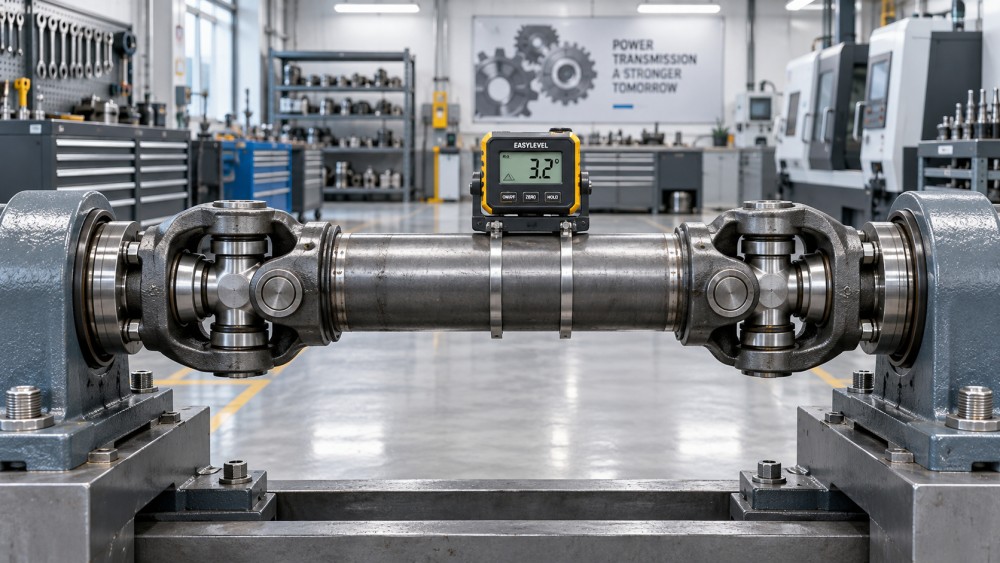
The geometry that prevents cyclic speed error
At zero operating angle, a cross-type universal joint transfers rotation smoothly. As the angle increases, the driven yoke accelerates and decelerates twice during each revolution relative to the driving yoke. This does not necessarily mean the shaft will shake; it becomes a problem when a second joint does not cancel the speed variation created by the first.
In a conventional two-joint driveline, the transmission or driving flange and the driven flange should generally be parallel in their working relationship, while the two joint operating angles should be close to equal. The shaft itself will often run at an angle; the goal is not always to make the shaft visually level. The goal is to ensure that the angle entering the shaft is correctly compensated by the angle leaving it.
Yoke phasing matters just as much. The yokes at both ends of the intermediate shaft normally need to be aligned in the intended plane. If a slip joint is reassembled one spline out of phase, the second joint cannot cancel the first joint’s velocity variation. The result can resemble imbalance, yet adding balance weights or replacing the shaft may not cure it.
Why equal angles are not always a visual judgment
Mounting points can be misleading. A gearbox output flange may be tilted downward, while the differential or driven machine input is tilted upward. The shaft may appear nearly straight, but the actual joint angles can differ significantly. Measure the angle of each component rather than estimating from the shaft’s appearance.
Use an inclinometer, digital angle gauge, or suitable driveline measuring tool on clean, stable reference surfaces. Measure the driving component, shaft tube, and driven component. The operating angle at each joint is the difference between the shaft angle and the angle of the component connected to that joint. On systems with more than one shaft section, measure every section separately. A center bearing changes the geometry and must not be treated as a passive support.
Check the installation conditions that alter alignment after assembly
Correct angles measured on a lift do not guarantee correct angles in service. A vehicle or machine may sit differently on its wheels, with hydraulic cylinders retracted, or with a working load applied. Rubber mounts can settle under torque. A center support bearing can shift when its bracket is tightened. On mobile equipment, axle movement through suspension travel may change both joint angle and slip-spline engagement.
Inspect the driveline at its normal operating height whenever possible. Where the equipment moves through a broad range of articulation, inspect the full expected travel. Pay close attention near compression, rebound, steering movement, or a raised implement position. A joint that has enough clearance at rest can bind when the shaft reaches its maximum working angle.
The slip section deserves the same attention as the joints. It must have sufficient engagement through the operating range, but it also needs room to compress. A shaft bottoming in the slip section transfers axial load into the universal joint bearings, yokes, transmission extension housing, or driven input. Too little spline engagement promotes torsional movement, fretting, and spline wear. Either condition can produce a noise that is incorrectly blamed on the cross assembly.
Mounts and supports are part of the alignment system
Transmission mounts, engine mounts, pump brackets, bearing pedestals, axle locating links, and center support bearing brackets all determine joint geometry. A mount that appears intact may still be too soft, collapsed, oil-contaminated, or separated internally. Under torque, the component can rotate enough to create unequal angles. Check for witness marks, distorted brackets, loose fasteners, and changes in clearance between the driveline and nearby components.
Center support bearings require especially careful positioning. Preload, bracket orientation, and support height can affect the operating angles of both shaft sections. Tightening the bearing support while the shaft is pulled to one side can introduce a permanent offset. Follow the equipment manufacturer’s specified support position rather than forcing the shaft into a visually convenient line.
Install the replacement joint without creating a new failure point
A replacement Universal Joint can be damaged during installation even when its dimensions are correct. Before pressing out the old cups, mark the shaft sections, flange positions, balance-weight orientation, and yoke relationship. These marks do not replace measurement, but they prevent accidental reversal or phase errors during reassembly.
- Clean the yoke bores, snap-ring grooves, and mating faces. Rust, burrs, paint buildup, or fragments from a failed bearing cup can prevent full seating.
- Compare the new joint with the removed part, including cup diameter, span, retention method, grease fitting location, and any offset or special design features.
- Press cups in squarely. Excessive hammering can damage needle bearings or distort the cup. If a cup stops unexpectedly, remove it and inspect rather than forcing it.
- Confirm that retaining clips fit fully in their grooves. A clip that will not seat usually indicates a cup is not fully installed, the wrong joint has been selected, or the yoke bore has been deformed.
- After assembly, move the joint through its full articulation range. It should pivot smoothly without tight spots, notchiness, or binding.
- Check end play according to the applicable service specification. A joint clamped too tightly can bind; excessive axial clearance allows impact loading and fretting.
Greaseable joints should be lubricated with the correct lubricant and without overpressurizing the seals. Apply grease until fresh lubricant appears at the seals where the joint design allows it, then remove excess from the surrounding area. A blocked passage, hardened old grease, or a damaged fitting must be addressed rather than compensated for with excessive pressure. For sealed joints, do not assume they are maintenance-free in the broader sense; inspect seal condition and operating environment even though routine greasing is not required.
Do not use a single-joint rule on every driveline design
Some systems use a double-Cardan arrangement, a constant-velocity joint, or multiple shaft sections because the driveline must operate at angles that a conventional two-joint system cannot handle smoothly. These designs have their own alignment requirements. A double-Cardan shaft commonly requires the pinion or driven flange to be oriented differently from a standard two-joint arrangement so that the joint at the opposite end operates correctly. Applying the “parallel flanges” rule without identifying the shaft design can create a vibration rather than eliminate one.
Similarly, a shaft with a center bearing has more than two operating angles, and an industrial pump drive may use flexible couplings or guard-supported shafts with different alignment limits. Confirm the arrangement from the equipment documentation and inspect the actual component configuration before making shims, changing mount height, or rotating a flange.
Separate misalignment wear from lubrication and contamination damage
Misalignment often leaves a pattern of cyclic loading: polished bearing tracks, fatigue spalling, uneven needle wear, or damage concentrated at one pair of cups. Lubrication failure can look similar, but it often brings dry discoloration, heat marks, seized needles, or heavy corrosion. Contamination is common where a shaft operates near water, abrasive dust, slurry, or damaged guards. Once seals are torn, even a correctly aligned joint may fail quickly.
These causes can overlap. A steep angle increases bearing movement and seal stress; a compromised seal admits abrasive material; lost lubricant accelerates wear; growing clearance then increases vibration. Correcting only one step in that chain may leave the system vulnerable. The repair should therefore include angle verification, inspection of supports and slip travel, correct joint installation, and a realistic lubrication or inspection interval for the operating environment.
When shaft condition must be checked before returning equipment to service
After a joint failure, inspect the complete shaft rather than treating the cross as an isolated consumable. Rotate the shaft and check for visible wobble, dented tubing, missing balance weights, damaged welds, worn flange pilots, elongated bolt holes, and rough or loose splines. Measure runout where the service procedure provides limits. A bent tube or distorted flange can overload new bearings immediately, even with acceptable joint angles.
Further assessment is warranted when vibration remains after phasing and operating angles have been corrected, when a yoke bore is cracked or spread, when the shaft has contacted a fixed structure, or when repeated joint failures occur under normal maintenance. In those situations, inspect the driveline as an assembly, including connected gearbox, axle, pump, or machine input bearings. Replacing another joint without identifying the movement or runout that caused the failure usually restarts the same wear cycle.
Related News
- How to Assess a Rigid Coupling Supplier for Bore Accuracy and Traceable QualityOct 08, 2026Tribology & Kinematics Expert
- Titanium Alloys Compared: Balancing Strength, Corrosion Resistance, and MachinabilityOct 08, 2026CNC Kinematics Architect
- Where Ductile Iron Dismantling Joints Reduce Alignment Risk in Water PipelinesOct 08, 2026Pipeline Metallurgy Scientist
- Selecting a Precision Bearing Sleeve: Fits, Runout, and Material ChoicesOct 08, 2026Tribology & Kinematics Expert
- Face Milling Cutters: How Insert Geometry Affects Finish on Steel and AluminumOct 08, 2026CNC Kinematics Architect
- Single-Acting Cylinders for Clamping: Stroke, Force, and Return Spring ConsiderationsOct 07, 2026Fluid Power Control Strategist