
Stepper Motor Couplings: Preventing Misalignment, Backlash, and Lost Motion
A positioning fault on a stepper-driven axis rarely announces itself as a coupling problem. The machine may begin with a faint rattle during rapid moves, a growing witness mark on a shaft, or parts that are consistently off by a small distance after direction changes. Maintenance teams often look first at drive current, acceleration, bearings, or controller parameters. Those checks matter, but the mechanical connection between motor and load deserves equal attention.
Well-chosen motion control couplings for stepper motors protect accuracy where torque leaves the motor shaft and enters a ball screw, lead screw, rotary table, gearbox, encoder, or conveyor drive. The wrong coupling—or a good coupling installed poorly—can turn small alignment errors into backlash, vibration, shaft stress, and apparent lost steps. For after-sales maintenance personnel, the goal is not simply to replace a worn part. It is to identify why the coupling is being asked to compensate for a larger mechanical problem.
Why a Small Coupling Can Create a Large Positioning Error
A stepper motor normally operates in an open-loop system: the controller commands a number of pulses and assumes the motor and mechanism followed them. If the axis does not reach the intended position, the cause may be electrical, but it may also be mechanical compliance or slipping at the coupling. This distinction is important. A motor that truly stalls has lost synchronism. A coupling that twists, shifts, or slips can create a similar process result without the motor necessarily missing a full step.
Every coupling has a torsional behavior. Under load, a flexible coupling deflects slightly before transmitting torque. Some deflection is necessary to accommodate normal shaft movement; too much creates a spring effect. During a reversal, the motor may rotate before the driven shaft responds fully. On a long screw or a high-inertia load, that delay becomes visible as lost motion, inconsistent edge location, poor contour accuracy, or oscillation after a stop.
Couplings also influence the life of components on both sides of the joint. If the motor shaft and driven shaft are forced into alignment by a rigid connection, radial and bending loads may be transferred into motor bearings, screw bearings, and gearbox input bearings. A flexible coupling reduces this stress, but it is not a substitute for correcting severe offset, shaft runout, or a distorted mounting plate.
Three Different Faults That Are Often Called “Backlash”
In service reports, “backlash” is frequently used for any inaccuracy after direction reversal. Separating the symptom into its actual source saves time and avoids replacing a coupling that is not the root cause.
- True coupling backlash is free angular movement between the hubs and the torque-transmitting element. It is common in worn jaw couplings, loose-key arrangements, damaged clamp hubs, or poorly fitted Oldham discs.
- Torsional wind-up is elastic twist under changing torque. There may be no clearance at all, yet the driven shaft lags behind the motor during acceleration or reversal.
- Transmission backlash comes from the ball screw nut, gearbox, belt drive, rack-and-pinion set, or other downstream component. The coupling may only make the condition easier to notice.
A useful field check is to lock out the machine, secure the axis safely, and mark both coupling hubs with a fine line across the joint. Apply a controlled manual load in both directions, following the equipment manufacturer’s safety procedures. If the marks separate before the load begins to move, inspect the coupling interface. If they remain aligned while the table or screw shows movement delay, investigate the downstream drive train. This simple observation is often more informative than adjusting the controller’s backlash compensation blindly.
Misalignment Is Not One Condition
Most flexible couplings are described as “misalignment compensating,” but the phrase can lead to unrealistic expectations. The shaft condition can involve parallel offset, angular offset, axial movement, or a mixture of all three.
Parallel misalignment means the shaft centerlines are offset but remain roughly parallel. Angular misalignment means the shafts meet at an angle. Axial displacement is movement along the shaft centerline, caused by thermal growth, bearing float, or assembly tolerance. A coupling may accommodate all three, yet its published ratings are limits, not recommended continuous operating targets. Running close to those limits increases restoring forces, heat, fatigue, and motion error.
For stepper applications, the practical question is not only “Will the coupling survive?” It is “Will the assembly retain repeatable position through the full motion cycle?” A coupling that survives a static alignment check may behave poorly when the motor bracket warms, a vertical axis changes load direction, or a screw end support shifts under thrust.
How Common Stepper Motor Coupling Designs Behave in Service
There is no universally best design. Selection should follow the axis duty, required positional repeatability, available installation space, torque profile, and realistic alignment condition.
Beam or Helical Couplings
Beam couplings use spiral cuts in a single metal body. They are compact, clean, and often used on small stepper motors driving lead screws, encoders, and light automation axes. Their one-piece construction eliminates mechanical backlash when correctly installed. They can tolerate modest angular and parallel offset, but their torsional stiffness varies widely with geometry. A long, multi-start helical cut may be forgiving of misalignment while feeling comparatively soft in reversal. On a high-precision or high-acceleration axis, that compliance can appear as settling time or following error.
Bellows Couplings
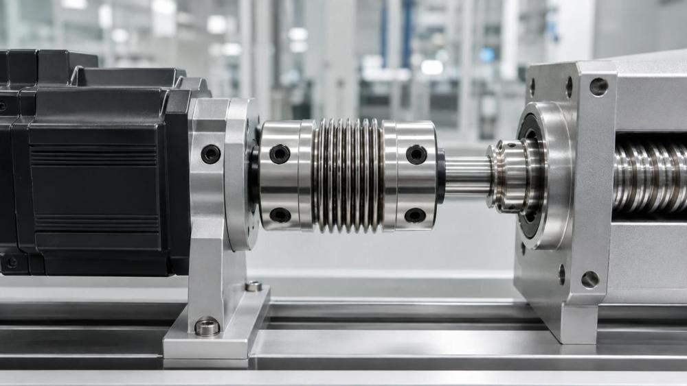
Metal bellows couplings combine hubs with a thin formed bellows element. They are valued where high torsional stiffness, zero backlash, and accurate angular transmission are needed, such as metrology equipment, rotary indexing, and precision screw drives. They can accommodate angular, parallel, and axial movement within specified limits, but they should not be installed into a visibly misaligned assembly. Bellows fatigue can develop when a coupling continuously flexes beyond its intended duty. Inspect for deformation, cracking, discoloration, or evidence that the bellows is rubbing nearby hardware.
Oldham Couplings
An Oldham coupling uses two hubs and a center disc that slides in perpendicular slots. Its major strength is handling parallel shaft offset. This makes it useful when mounting tolerances are difficult to control or when shafts remain laterally displaced. However, the center element is a wear component. Disc material affects damping, torque capacity, chemical resistance, and service life. As the disc wears, rotational clearance can increase. In a stepper axis that reverses frequently, maintenance teams should treat disc condition as a scheduled inspection item rather than waiting for a positioning complaint.
Jaw Couplings
Jaw couplings transmit torque through an elastomer spider between two hubs. They provide useful vibration damping and can soften shock loads. For general machinery, that is often an advantage. For a tightly controlled stepper axis, the elastomer’s torsional deflection and aging characteristics must be considered. A loose, hardened, compressed, or chemically attacked spider can produce noticeable reversal error. Jaw designs may suit robust indexing, pumps, feeders, and less demanding positioning systems, but they are not automatically the first choice for sub-millimeter motion accuracy.
Disc and Rigid Couplings
Disc couplings offer high torsional stiffness and can be appropriate for higher torque or precision applications when alignment is carefully controlled. Rigid couplings transmit motion with virtually no coupling compliance, but they tolerate almost no misalignment. They belong only in assemblies where shaft alignment, bearing support, and structural stability are verified to a high standard. Installing a rigid coupling to “remove backlash” from a poorly aligned machine simply transfers the problem into bearings and shafts.
Selection Should Start at the Axis, Not at the Motor Frame
A coupling bore that matches the motor shaft diameter is only the beginning. Maintenance replacements should be reviewed against the complete application. Record the motor shaft size, driven shaft size, usable hub length, keyway or flat arrangement, maximum outside diameter, and required clearance to guards or sensors. Then examine motion requirements: peak torque during acceleration, load inertia, reversal frequency, speed range, and the consequences of a small positioning deviation.
Torsional stiffness deserves particular attention. A very compliant coupling may reduce vibration in one system but create unacceptable wind-up in another. Conversely, an extremely stiff coupling on an imperfectly aligned assembly can increase bearing load and transmit resonance. The preferred balance is usually a zero-backlash design with enough misalignment capacity for the actual machine build, not the largest theoretical capacity advertised in a catalog.
Hub attachment is equally important. Set-screw hubs are common and convenient, but they demand a clean shaft, correct screw position, and tightening to the manufacturer’s torque. Where possible, a screw should seat on a shaft flat rather than a rounded surface. Clamp-style hubs generally provide more even grip and reduce shaft damage, making them attractive for frequent service or precision assemblies. Keyed shafts, splines, and shrink-disc arrangements have their own requirements; none eliminates the need to verify concentricity and secure torque transmission.
Installation Practices That Prevent Future Lost Motion
Many coupling failures begin during a rushed repair. A technician may slide the coupling fully against the motor shoulder, tighten one set screw, and assume the job is complete. That can preload the coupling, block axial movement, or leave too little shaft engagement on the opposite hub.
Before fitting the new part, clean both shafts and inspect them under good light. Remove burrs, corrosion, adhesive residue, and raised metal around old set-screw marks. Check for shaft wobble by rotating the shaft and observing runout with a dial indicator where precision warrants it. A bent screw shaft, damaged motor shaft, or worn support bearing will defeat even the best coupling.
Set the coupling according to its specified shaft insertion depth and hub gap. Some designs require a defined separation between shaft ends so the flexible element can move correctly. Do not force the hubs together until their shaft ends touch unless the manufacturer explicitly permits it. Position the motor so its shaft centerline is as close as practical to the driven shaft centerline, then tighten mounting hardware gradually while checking that alignment does not shift.
For clamp hubs, alternate tightening between screws where applicable. For set-screw designs, use the stated tightening torque and any approved thread-locking method. Over-tightening can distort a small hub or damage a motor shaft; under-tightening permits micro-slip that gradually polishes the shaft and destroys positional integrity. After commissioning, recheck fasteners after the machine has completed an initial operating period, especially on high-vibration equipment.
A Practical Troubleshooting Route for Maintenance Teams
When a stepper-driven machine shows drift, noise, poor repeatability, or direction-change error, avoid changing several variables at once. Start by reproducing the fault with a short, safe motion program. Note whether the error occurs only under acceleration, only at reversal, after warm-up, or at one section of travel. These patterns narrow the search.
- Confirm motor and drive basics. Check power supply stability, driver fault indications, current settings, acceleration and speed limits, wiring integrity, and excessive motor temperature.
- Inspect the coupling externally. Look for shifted hub position, loose fasteners, metallic dust, cracked flexible elements, spider deterioration, rub marks, and shaft fretting.
- Test for rotational clearance. With power isolated, observe relative hub movement under light reversing torque. Any unexpected movement at the shaft-to-hub connection is a priority finding.
- Check alignment and support bearings. Verify bracket stiffness, screw support condition, gearbox input play, and shaft runout. A coupling repeatedly failing in the same way usually signals an external alignment or loading issue.
- Evaluate the load path. A binding slide, contaminated linear guide, overtightened seal, or changing process load can raise torque demand enough to cause true step loss. The coupling is then a witness, not the cause.
Do not assume that replacing a flexible coupling with a stiffer one will cure all lost motion. If the original coupling is intact and correctly clamped, the better remedy may be reduced acceleration, correction of a binding axis, improved motor sizing, or repair of a worn ball screw assembly. Mechanical diagnosis works best when the motor, coupling, shafts, bearings, and load are treated as one motion system.
Inspection Intervals Should Follow Duty, Not Just Calendar Dates
On a lightly used machine in a clean environment, coupling inspection may fit naturally into periodic preventive maintenance. On packaging lines, automated handling equipment, machine tools, or dusty industrial systems with constant reversing, condition checks should be more frequent. Heat, washdown chemicals, cutting fluid mist, abrasive contamination, and repeated shock loads can shorten the life of flexible elements and loosen fasteners.
Keep a simple record of coupling type, bore sizes, installation date, tightening method, observed alignment condition, and any replacement reason. Over time, this record reveals useful patterns: the same axis loosening repeatedly, one coupling material degrading near a process chemical, or a motor bracket moving after thermal cycling. These are the details that turn reactive repair into reliable maintenance planning.
What Reliable Motion Really Looks Like
A healthy stepper coupling is easy to overlook. It transmits commanded torque without slip, adds no measurable free play, accommodates normal machine movement without overloading bearings, and remains stable through thousands of reversals. That quiet reliability is especially important in machinery where a small error can become scrap, a rejected assembly, or an unexpected service call.
For maintenance personnel, the most effective approach is disciplined rather than dramatic: select motion control couplings for stepper motors based on torsional behavior and real alignment needs; install them with clean shafts and controlled hub engagement; and investigate recurring wear as evidence of a system-level issue. When coupling condition becomes part of routine motion-system inspection, misalignment, backlash, and lost motion are far less likely to become production problems.
Related News
- How to Assess a Rigid Coupling Supplier for Bore Accuracy and Traceable QualityOct 08, 2026Tribology & Kinematics Expert
- Titanium Alloys Compared: Balancing Strength, Corrosion Resistance, and MachinabilityOct 08, 2026CNC Kinematics Architect
- Where Ductile Iron Dismantling Joints Reduce Alignment Risk in Water PipelinesOct 08, 2026Pipeline Metallurgy Scientist
- Selecting a Precision Bearing Sleeve: Fits, Runout, and Material ChoicesOct 08, 2026Tribology & Kinematics Expert
- Face Milling Cutters: How Insert Geometry Affects Finish on Steel and AluminumOct 08, 2026CNC Kinematics Architect
- Single-Acting Cylinders for Clamping: Stroke, Force, and Return Spring ConsiderationsOct 07, 2026Fluid Power Control Strategist