
Selecting Splined Shafts: Fit Class, Torque Capacity, and Misalignment Limits
Selecting splined shafts is not a matter of matching an outside diameter and tooth count to an existing drawing. In a power transmission assembly, the spline must transfer torque while preserving positional accuracy, accommodating manufacturing variation, surviving repeated load reversals, and avoiding wear mechanisms that often remain invisible until the system begins to vibrate or lose motion control.
For technical evaluators, the central question is not whether a spline connection can transmit the stated nominal torque. Most properly sized splines can do that under ideal conditions. The more useful question is whether it can maintain its function over the intended duty cycle, with the actual alignment, lubrication condition, manufacturing capability, assembly method, and load spectrum of the machine.
This distinction matters in gearboxes, construction equipment, machine tools, pumps, industrial drives, agricultural machinery, wind-related equipment, and automated handling systems. A spline that performs adequately in a static calculation may still develop fretting corrosion, backlash, tooth-edge loading, or fatigue cracks in service. Selection therefore requires a combined review of fit class, tooth geometry, engagement length, material condition, torque path, and allowable misalignment.
Start with the Function of the Connection
A splined shaft can serve different mechanical purposes, and those purposes should determine the selection criteria. Fixed connections generally prioritize torque transmission and rotational positioning. Sliding splines must also support axial movement, often under load. In some assemblies, the spline is expected to allow thermal expansion or suspension travel; in others, it must hold two components with very little rotational clearance.
These are not interchangeable duties. A close fit that improves torsional rigidity in a fixed hub may create unacceptable sliding resistance in a telescoping driveline. Conversely, a loose fit that permits movement can produce backlash and impact loading in a servo-driven axis. Before selecting dimensions, evaluators should define whether the connection is primarily:
- a fixed torque interface between shaft and hub;
- a sliding torque interface requiring repeated axial travel;
- a location feature that controls angular indexing;
- a replaceable wear interface intended for periodic service; or
- a legacy replacement constrained by an existing mating component.
That functional definition should appear in the engineering specification. A drawing that states only “splined shaft” leaves critical decisions to interpretation, especially when the supplier must choose machining method, inspection practice, and fit tolerance.
Fit Class Is a System Decision, Not a Single Tolerance
Fit class is often treated as a simple preference for “tight” or “loose.” In reality, the fit results from the interaction of external spline tooth thickness, internal spline space width, pitch diameter variation, tooth flank form, lead, concentricity, and the quality of the mating parts. The measured clearance at one point is not enough to predict how load will distribute across the engaged teeth.
A close fit can reduce rotational play and improve response in applications such as precision rotary equipment, controlled actuators, and certain gearbox interfaces. But very limited clearance also increases sensitivity to manufacturing variation, coating thickness, debris, thermal expansion, and shaft deflection. If assembly requires force where the design did not intend an interference condition, the resulting contact pattern may be highly uneven.
For sliding applications, enough clearance is needed to maintain movement after lubrication condition, contamination, temperature, and surface finish are considered. Excessive clearance, however, permits repeated micro-impact between flanks. This can create fretting debris, increase backlash, and progressively damage the contact surfaces. The correct fit is therefore the one that supports the operating motion and load distribution, not automatically the closest fit a supplier can manufacture.
Technical teams should ask suppliers how the fit is controlled and verified. Depending on the spline standard and component type, this may involve functional gauges, measurement over pins or balls, coordinate measurement, dedicated spline inspection equipment, or a combination of methods. A dimensional report that lists only major diameter and minor diameter provides limited assurance if the working flanks and effective pitch diameter are not adequately controlled.
When replacing an existing assembly, fit evaluation should include the mating part. Installing a newly manufactured shaft into a worn hub can conceal the source of excessive backlash or create only partial tooth contact. In repair programs, shaft and hub wear should be assessed as a pair rather than approved independently.
Torque Capacity Depends on More Than Tooth Count
Torque capacity is commonly estimated from spline geometry, allowable tooth flank pressure, engagement length, and material strength. Those calculations are necessary, but their result is only as reliable as the assumptions behind load sharing. In an ideal spline connection, multiple teeth distribute load relatively evenly. In service, manufacturing errors and shaft or hub deflection can cause a small portion of the teeth to carry much more load than expected.
The basic design review should account for continuous torque, peak torque, reversing torque, start-stop events, shock loads, and overload events. A conveyor drive with smooth, near-constant torque presents a different risk profile from a crusher drive, hydraulic winch, press, or robot axis that sees abrupt reversal. The nominal motor rating alone is not a sufficient input.
Tooth flank pressure is one concern. Tooth-root bending fatigue is another, especially where torque cycles repeatedly reverse. In high-cycle applications, local stress concentration caused by tooth form error, machining marks, poor fillet condition, or decarburization after heat treatment can become more important than the nominal static strength of the shaft material.
There is a persistent assumption that a longer spline always solves a torque problem. Increasing engagement length can help, but only when the load remains reasonably distributed along that length. A long connection with misalignment or inadequate lead control may load primarily at one end. In that condition, additional nominal contact area exists on the drawing but not in the actual force path.
Similarly, selecting a higher-strength shaft steel does not automatically increase system capacity. The internal spline hub may become the limiting component, or the connection may fail through fretting wear before material yield is approached. Capacity must be assessed at the interface level, including both members, their support stiffness, and their service environment.
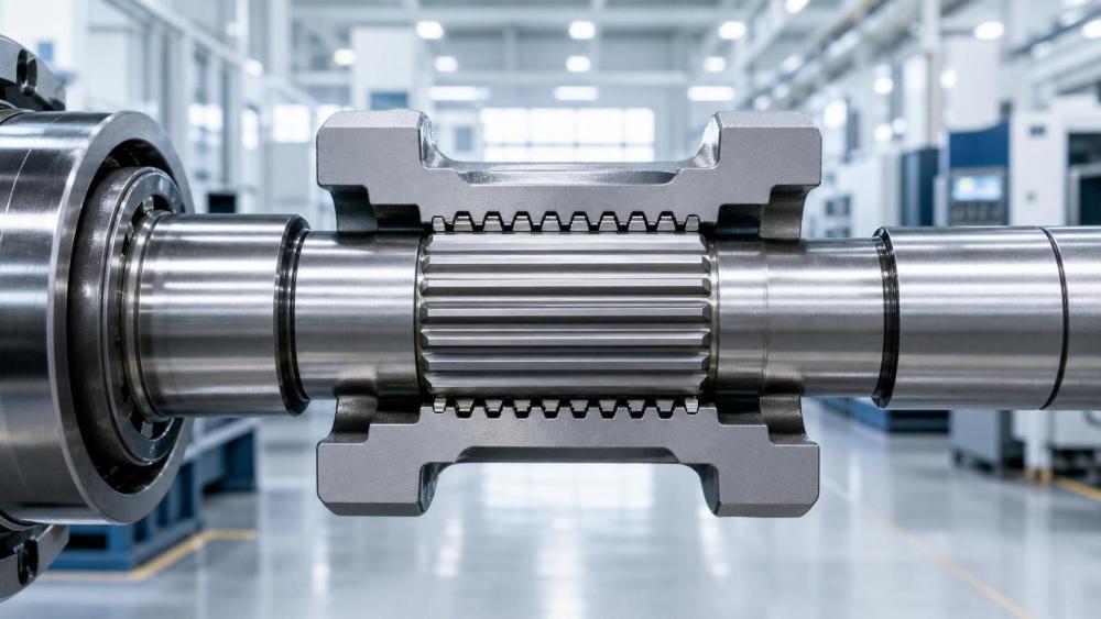
Misalignment Has to Be Treated as an Operating Condition
Splines are sometimes expected to compensate for angular or parallel misalignment because they are more forgiving than a rigid keyed connection in certain arrangements. That expectation needs careful qualification. A conventional involute spline is not a substitute for a properly selected flexible coupling, universal joint, or alignment correction strategy.
Angular misalignment can shift contact toward tooth edges and toward one end of the engagement. Parallel offset, runout, and shaft bending can have similar effects. The result is higher local stress, unstable wear, increased friction during axial sliding, and fretting at locations where relative movement is small but repetitive. The assembly may initially appear acceptable, then develop red-brown debris, polished tooth flanks, noise, or torsional looseness after a relatively short period.
The permissible misalignment is not a universal catalogue number. It depends on spline length, module or diametral pitch, pressure angle, flank clearance, tooth crowning or modification, shaft diameter, hub geometry, bearing spacing, load direction, and whether the spline slides in operation. A value cited for one driveline design should not be applied directly to a compact gearbox or precision actuator.
Technical evaluators should distinguish between initial assembly alignment and operating alignment. A machine can be aligned at installation but move under thermal growth, frame distortion, bearing wear, hydraulic cylinder side load, or external vibration. The relevant limit is the maximum condition during operation, including reasonable manufacturing and assembly variation.
Where Misalignment Risk Is Commonly Underestimated
- Long sliding shafts supported by bearings with wide spacing or flexible mounts.
- Heavy equipment drivelines exposed to articulation, chassis movement, and shock.
- Gearbox outputs where bearing clearance changes under radial load.
- Hydraulic pump and motor connections with installation-induced offset.
- Assemblies using thin-walled hubs that deform under clamp load or transmitted torque.
- Retrofit applications where the original bearing, coupling, or housing condition is unknown.
Where misalignment cannot be eliminated, designers may need a shorter spline engagement, an appropriate crowned or modified tooth design, a separate flexible coupling, revised bearing support, or a different torque-transfer arrangement. The best solution depends on the machine architecture; simply increasing spline clearance may reduce binding while creating backlash and wear elsewhere.
Material, Heat Treatment, and Surface Condition Need a Linked Review
Material selection should begin with the expected failure mechanism. For a heavily loaded fixed spline, tooth-root fatigue and flank contact stress may dominate. For a sliding spline, adhesive wear, fretting, corrosion, and lubricant breakdown may determine life. For outdoor machinery, surface protection and contamination resistance can be as important as nominal mechanical strength.
Alloy steels with suitable heat treatment are widely used for demanding shafts, but the chosen process must match the geometry and duty. Through-hardening can provide strength but may not offer the same surface wear performance as an engineered case-hardening or nitriding approach. Case hardening can improve contact durability, yet its case depth, core support, distortion control, and post-treatment inspection must be appropriate for the tooth size and load.
Heat treatment also changes the manufacturing sequence. Splines cut before hardening may distort during treatment; splines finished after hardening require equipment and tooling capable of maintaining the specified form and surface condition. Procurement documents should state the required material grade, heat-treatment condition, hardness range, and any case-depth or microstructure requirements that are critical to function. Where failure consequences are high, material certificates and hardness verification should be part of the quality package.
Surface finish is not cosmetic. Rough machining marks across the tooth flank can accelerate wear and encourage lubricant film breakdown. At the same time, an extremely smooth finish is not automatically optimal when the lubrication regime, coating, and running-in behavior have not been considered. The practical objective is a controlled, repeatable surface compatible with the lubrication method and expected contact pressure.
Lubrication and Contamination Often Decide Service Life
Many spline failures described as “overload” failures begin as lubrication failures. Without an adequate lubricant film, small cyclic movements between loaded tooth flanks produce fretting. The debris generated by fretting becomes abrasive, increasing clearance and accelerating further wear. In sliding connections, inadequate lubrication may also cause stick-slip motion, high axial actuation force, or galling.
The selection process should define the lubrication regime rather than merely calling for grease. Relevant questions include lubricant type, replenishment interval, access to the lubrication point, temperature range, sealing arrangement, water exposure, particulate contamination, and whether the spline is assembled once or moves throughout service. Grease selection may need to account for high contact pressure, washout resistance, corrosion protection, and compatibility with adjacent seals or coatings.
Sealing is particularly important in mobile equipment, mining, agricultural machinery, and external infrastructure equipment. A high-quality spline manufactured to close tolerances will not retain its performance if abrasive contamination reaches the contact surfaces. Conversely, overly aggressive seals can increase sliding resistance or retain water if the housing design does not provide proper drainage. The spline, lubricant, seals, and housing should be reviewed as one tribological system.
Specify What the Supplier Must Demonstrate
For purchasing and technical approval, a usable specification goes beyond a nominal spline designation. It should identify the applicable drawing revision and standard, tooth form, fit requirement, material, heat treatment, surface treatment where relevant, engagement length, and acceptable inspection method. It should also clarify whether the shaft will mate with an existing component, a supplied hub, or a separately procured part.
Supplier evaluation should focus on process capability as well as equipment claims. The key questions are whether the manufacturer can consistently produce the required geometry, manage heat-treatment distortion, inspect functional dimensions, maintain traceability, and protect the teeth during packing and transport. For critical applications, requesting first-article inspection results, functional gauge records, hardness reports, and evidence of calibration is more informative than relying on general statements about precision machining.
It is also worth confirming how the supplier handles deburring. Burrs at tooth edges can interfere with assembly, damage mating splines, or become contamination in a lubricated system. However, uncontrolled edge breaking can alter the effective tooth form. The requirement should call for controlled deburring appropriate to the drawing and fit function.
A Practical Review Before Release
Before releasing a splined shaft for production or procurement, technical evaluators should be able to answer a short set of operational questions: What torque spectrum reaches the connection? Is the spline fixed or sliding? What misalignment occurs during real operation? Which component limits the interface capacity? How will the teeth be lubricated and sealed? Which dimensions and material conditions will be functionally inspected? And what is the replacement strategy if the mating hub is already worn?
When these questions have clear answers, spline selection becomes a controlled engineering decision rather than a drawing interpretation exercise. The objective is not the most restrictive fit, the hardest material, or the largest available spline. It is a connection whose geometry, contact behavior, manufacturing control, and service conditions remain compatible through the life of the equipment.
Related News
- How to Assess a Rigid Coupling Supplier for Bore Accuracy and Traceable QualityOct 08, 2026Tribology & Kinematics Expert
- Titanium Alloys Compared: Balancing Strength, Corrosion Resistance, and MachinabilityOct 08, 2026CNC Kinematics Architect
- Where Ductile Iron Dismantling Joints Reduce Alignment Risk in Water PipelinesOct 08, 2026Pipeline Metallurgy Scientist
- Selecting a Precision Bearing Sleeve: Fits, Runout, and Material ChoicesOct 08, 2026Tribology & Kinematics Expert
- Face Milling Cutters: How Insert Geometry Affects Finish on Steel and AluminumOct 08, 2026CNC Kinematics Architect
- Single-Acting Cylinders for Clamping: Stroke, Force, and Return Spring ConsiderationsOct 07, 2026Fluid Power Control Strategist