
Selecting Pinion Gears for Rack Drives: Tooth Profile, Load, and Backlash Criteria
A rack drive can look straightforward on a layout drawing: a straight rack, a round pinion, and a motor or gearbox converting rotation into linear travel. Yet many motion problems begin when the pinion is selected as if it were merely a matching gear. Excessive noise at speed, tooth wear near the end of travel, inconsistent positioning, drive vibration, and premature bearing damage often trace back to the same source: the pinion, rack, mounting arrangement, and duty cycle were not evaluated as one system.
When selecting pinion gears for rack drives, technical evaluators need to look beyond module or diametral pitch. Tooth profile, transmitted tangential force, pitch diameter, face width, tooth hardness, mounting accuracy, lubrication, and allowable backlash all shape real machine behavior. The right choice depends not only on how much load the system moves, but also on whether it must position precisely, reverse frequently, survive contamination, or run continuously at high speed.
This guide provides a practical framework for evaluating rack-and-pinion components in machine tools, gantries, automation lines, lifting equipment, industrial doors, material handling systems, and heavy machinery.
Start with the motion requirement, not the gear catalog
Before comparing pinion options, define what the drive is expected to do over its full operating cycle. A rack drive used to open a protective enclosure has very different requirements from one moving a CNC gantry or positioning a welding robot. The first may tolerate visible backlash and intermittent engagement. The second may require repeatable reversals, controlled acceleration, and stable motion across a long travel length.
Collect the operating data in a form that can be reviewed by mechanical, controls, and procurement teams:
- Required linear force, including friction, gravity, process loads, and acceleration force
- Maximum and normal travel speed
- Acceleration, deceleration, emergency-stop loads, and reversal frequency
- Positioning accuracy, repeatability, and permitted lost motion
- Duty cycle and expected service life
- Ambient contamination, humidity, temperature, and washdown exposure
- Available gearbox ratio, motor torque, and mounting space
- Rack length, section joints, support structure stiffness, and installation tolerances
This information prevents a common mistake: choosing a larger pinion only because the application has a high load. A larger pitch diameter can increase tooth engagement and reduce contact stress, but it also changes the torque requirement, linear resolution, inertia, and available acceleration. The best pinion is the one that balances the complete motion system rather than maximizing one parameter in isolation.
Tooth profile: matching geometry is only the first check
For most industrial rack drives, the pinion and rack must share the same fundamental tooth system. In metric gearing, this means the same module, pressure angle, and tooth form. In inch-based systems, the equivalent requirements are diametral pitch and pressure angle. A mismatch may appear to mesh during a hand test, but it produces poor contact, accelerated wear, irregular motion, and potentially damaged tooth flanks.
Pressure angle and load transfer
The pressure angle determines the direction in which tooth forces are transmitted. A standard industrial pressure angle is widely used because it offers a practical balance of tooth strength, availability, and interchangeability. Higher pressure-angle systems can provide stronger tooth bases and greater resistance to bending, but they may introduce higher radial forces into pinion bearings and supporting structures.
That radial force matters. In a lightly built carriage or a gearbox with limited output bearing capacity, a pinion selected for tooth strength alone may transfer unwanted deflection into the drivetrain. The result can be a changing mesh condition along the rack, especially over long travel distances or across rack joints.
Spur versus helical pinions
Spur pinions are simple, economical, and easy to inspect. Their teeth engage across the face width at essentially the same time, which makes them appropriate for many moderate-speed drives where straightforward assembly and serviceability are priorities. Their limitations become more apparent when smoothness, noise, or high-speed travel is important.
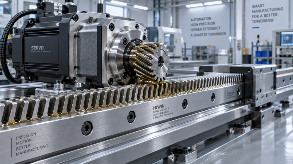
Helical rack-and-pinion drives provide progressive tooth engagement. More than one tooth can share the load during meshing, helping reduce vibration and improve running smoothness. This is especially useful for long-stroke gantries, automated handling equipment, and machine axes where a harsh engagement feel can affect both mechanical wear and control performance.
The trade-off is axial thrust. A helical pinion creates an axial load that the gearbox or pinion shaft bearings must absorb. Helical racks also require the correct helix hand and compatible geometry; a pinion cannot be mixed casually with a rack that has a different helix angle or handedness. If the system includes a preloaded dual-pinion arrangement, the mechanical layout becomes still more important.
Root form, tooth count, and undercut risk
Small pinions are attractive because they create high linear resolution for a given encoder count and can fit compact gearboxes. However, very low tooth counts may weaken the tooth root or introduce undercutting, depending on the gear geometry. Small pitch diameters also mean fewer teeth are engaged at a time and higher pinion rotational speed for the same linear travel speed.
For heavily loaded applications, increasing the pinion diameter or face width can be more effective than simply selecting a harder material. A larger pinion usually improves the contact condition and distributes work over more tooth surface. It may, however, reduce mechanical advantage at the drive output. The motor and reducer must be checked again after any geometry change.
Convert the application load into tooth forces
Pinion gear selection should be based on the tangential force at the pitch circle, not only on motor nameplate torque. The basic relationship is:
Ft = 2T / d
Where Ft is tangential force, T is torque at the pinion, and d is pinion pitch diameter. This force is what drives the rack linearly. Conversely, required pinion torque can be estimated from the required linear force and pitch diameter:
T = Ft × d / 2
These equations are useful, but the load entered into them must reflect the actual machine. Include sliding friction from guideways, cable carrier resistance, seal drag, grade or vertical lifting force, process resistance, and acceleration. For a moving axis, acceleration force is calculated from moving mass and required acceleration. A lightly loaded carriage can demand substantial torque during rapid acceleration, while a vertical axis may be governed by static gravitational load.
Do not size from average force alone. Review at least three conditions: normal running, peak acceleration or process load, and abnormal but credible events such as a controlled emergency stop, jam detection threshold, or end-of-stroke impact. The allowable tooth load must also account for the selected service factor, which rises when shock, frequent starts, reversing motion, uneven load distribution, or uncertain alignment is present.
Bending strength and contact fatigue are different checks
A pinion tooth can fail through root bending or through surface contact fatigue. Bending strength concerns the tooth root, where repeated tangential loading may initiate a crack. Contact strength concerns the tooth flanks, where high Hertzian stress can lead to pitting, micropitting, scuffing, or surface distress.
For slow, highly loaded equipment, bending strength may dominate. For high-cycle drives with hardened teeth and long operating hours, contact fatigue and lubrication quality often become the limiting factors. The rack should be evaluated at the same time. A hardened pinion paired with a softer rack may shift wear into the rack, which is often the more difficult and expensive component to replace.
Use the manufacturer’s allowable load ratings with care. Confirm whether the rating assumes continuous or intermittent duty, a particular hardness combination, adequate lubrication, a specified face-width engagement, and ideal alignment. If the supplier provides gear-rating calculations based on recognized standards, those calculations should reflect the installed drive configuration rather than a catalog maximum.
Material and heat treatment should follow the failure mode
Material selection is not a simple choice between “steel” and “hardened steel.” It is a decision about wear, impact resistance, manufacturability, lubrication, and replacement strategy.
Through-hardened steel pinions offer a relatively uniform hardness through the section and can be suitable for robust general machinery. Induction-hardened or case-hardened teeth provide a hard wear-resistant surface with a tougher core beneath it, making them attractive for demanding motion axes and high-cycle industrial drives. Ground tooth flanks can improve mesh consistency and reduce the variation that becomes noticeable in precision positioning applications.
A hardened rack-and-pinion set generally offers better wear life than an untreated pair, but hardness must be matched thoughtfully. In some serviceable designs, it may be acceptable for one component to wear preferentially if replacement is easy and planned. In long gantries, however, treating the rack as a sacrificial component can create substantial maintenance cost and downtime.
Corrosion is another material question. Humid production areas, water-treatment equipment, outdoor machines, and washdown environments may require protective coatings, stainless-compatible solutions, enclosed gearing, or lubrication selected for water resistance. A corrosion-resistant surface that compromises tooth geometry or lubricant adhesion is not automatically the better answer; the operating environment must be considered as a whole.
Backlash is a system characteristic, not a single catalog value
Backlash is the clearance between mating tooth flanks. Some clearance is necessary to accommodate manufacturing variation, thermal effects, lubricant film, and installation realities. But excessive backlash appears as lost motion when direction changes. For a positioning axis, that lost motion may show up as following error, contouring inaccuracy, or a distinct knock during reversal.
The allowable backlash depends on function. A conveyor or manually positioned industrial guard may work reliably with a conventional single-pinion mesh. A laser cutting gantry, inspection system, or precision machine axis often needs much tighter control. In those applications, designers may use a spring-preloaded dual-pinion drive, an electronically controlled dual-drive arrangement, or a gearbox with a backlash-management strategy.
Preload reduces or eliminates flank clearance by applying opposing torque between two meshing pinions or gear elements. It improves reversal behavior, but it also increases tooth contact force, friction, heat generation, and wear. A preloaded system should never be specified without checking motor torque reserve, pinion and rack load capacity, bearing load, lubricant behavior, and thermal expansion over the operating range.
It is also important to separate backlash from positioning accuracy. A low-backlash pinion does not correct pitch variation in the rack, mounting errors, gearbox transmission error, flexible machine frames, encoder resolution limits, or control tuning problems. Evaluators should define the permitted error budget for the entire axis, then assign reasonable limits to each component.
Mounting accuracy can preserve—or erase—the value of a good pinion
Even a precisely machined pinion will perform poorly if the rack is mounted on an uneven or flexible surface. Changes in center distance alter tooth contact and backlash. Misalignment across the rack face concentrates load near one edge. Rack joints can create a noticeable bump if pitch continuity is not controlled during installation.
For long rack sections, review the straightness of the mounting datum, parallelism to the linear guide, joint alignment method, and fastening sequence. The rack should be supported continuously enough to prevent local bending under load. The pinion shaft and gearbox mount must be rigid enough that torque does not push the pinion away from the rack under peak force.
Lubrication and contamination determine long-term behavior
Rack drives are often exposed more directly than enclosed gears. Dust, metal chips, abrasive particles, washdown fluid, and insufficient lubricant can rapidly change the tooth surface condition. A dry-looking rack is not always under-lubricated, but polished flanks, discoloration, scoring, or abrasive paste around the teeth are warning signs that deserve investigation.
Select lubrication according to speed, load, temperature, and environmental exposure. Grease is common for open rack systems, while oil-based arrangements may suit enclosed or continuously operating drives. The lubricant must reach the active tooth flanks consistently; a lubrication point located near the rack but not delivering into the mesh does little to protect it. Automatic lubrication can improve consistency, provided the delivery rate is matched to the duty cycle and does not attract excessive debris.
In contaminated environments, protective bellows, rack covers, wipers, or enclosed drive layouts may deliver more value than a higher gear grade alone. Maintenance planning should include periodic inspection of tooth flanks, pinion bearing play, lubricant condition, fastener torque, and mesh behavior at rack joints.
A practical approval checklist for technical evaluators
Before releasing pinion gears for rack drives to procurement or production, confirm that the proposed set answers the following questions:
- Do rack and pinion match in module or pitch, pressure angle, tooth form, and—for helical systems—helix angle and hand?
- Has tangential force been calculated for peak operating conditions, not just steady travel?
- Are tooth bending and contact-load ratings adequate after service factors, duty cycle, and preload are considered?
- Does the pinion diameter provide a sensible balance between torque demand, speed, resolution, and tooth engagement?
- Are material hardness and surface treatment appropriate for wear, impact, corrosion, and replacement access?
- Is the backlash requirement tied to the complete axis accuracy budget rather than an isolated component specification?
- Can the structure, bearings, gearbox output, and rack mounting maintain alignment under load?
- Is there a realistic lubrication and contamination-control plan for the installed environment?
The strongest rack drive selections are rarely the most expensive or the most heavily specified in every category. They are the combinations in which tooth geometry, load capacity, backlash control, support stiffness, and maintenance conditions all support the machine’s intended job. By evaluating those factors together, engineers can choose a pinion that delivers predictable linear motion not only during commissioning, but through the long operating life that industrial equipment is expected to provide.
Related News
- How to Assess a Rigid Coupling Supplier for Bore Accuracy and Traceable QualityOct 08, 2026Tribology & Kinematics Expert
- Titanium Alloys Compared: Balancing Strength, Corrosion Resistance, and MachinabilityOct 08, 2026CNC Kinematics Architect
- Where Ductile Iron Dismantling Joints Reduce Alignment Risk in Water PipelinesOct 08, 2026Pipeline Metallurgy Scientist
- Selecting a Precision Bearing Sleeve: Fits, Runout, and Material ChoicesOct 08, 2026Tribology & Kinematics Expert
- Face Milling Cutters: How Insert Geometry Affects Finish on Steel and AluminumOct 08, 2026CNC Kinematics Architect
- Single-Acting Cylinders for Clamping: Stroke, Force, and Return Spring ConsiderationsOct 07, 2026Fluid Power Control Strategist