
Selecting Ball Screw Assemblies for Injection Molding: Load, Speed, and Repeatability
A molding cell can appear healthy during a short trial and still develop motion problems once production settles into long runs. The platen closes, the injection unit advances, and the controller reports no immediate fault. Yet operators begin to notice small changes: a mold half does not return to the same position as cleanly as before, a transfer point becomes harder to hold, or a high-speed cycle produces more vibration than the previous setup. These symptoms are often blamed first on servo tuning, lubrication, or mold condition.
In many cases, the root issue starts earlier, when the linear drive was selected mainly by nominal diameter, catalog load rating, or an assumed axis speed. For ball screw assemblies for injection molding machines, that shortcut can create a mismatch between the screw, the duty cycle, the support arrangement, and the actual loads seen during molding. The consequences may include lost repeatability, heat growth, rising torque demand, premature bearing wear, and avoidable downtime during mold changes or maintenance.
The useful question is not simply, “Which screw fits this axis?” It is: “Which assembly can repeatedly convert motor torque into the required linear motion under this machine’s real loading, speed profile, temperature range, and accuracy demands?” Answering it requires looking at the whole motion chain rather than treating the screw as an isolated catalog component.
Begin with the motion event that causes the concern
Injection molding machines use ball screws in different ways. An electric injection axis may require rapid acceleration, controlled forward thrust, a holding phase, and accurate recovery movement. A clamp or platen-related axis may see large external forces, changing load directions, and a long unsupported stroke. Auxiliary axes, such as ejectors or dosing mechanisms, usually have smaller loads but may cycle very frequently.
Those differences matter because a screw that is comfortable on a short, lightly loaded actuator may not be appropriate for an injection axis that repeatedly moves at high speed and then pushes against process resistance. Before comparing suppliers or configurations, separate the application into individual motion segments:
- rest-to-speed acceleration;
- constant-velocity travel;
- deceleration and reversal;
- material injection or pressure-holding travel;
- screw recovery, ejector action, or other return motion;
- dwell periods, during which heat may dissipate unevenly.
A single “maximum load” and “maximum speed” entry does not describe this sequence well enough. The sizing calculation needs the load and speed associated with each segment, plus the number of repetitions expected during normal production. This is especially important where a machine runs several molds with different cycle patterns. Selecting only for the easiest mold can leave little margin when a heavier tool or faster program is introduced.
Translate process requirements into screw loads
The axial force at the ball nut is not identical to the molding pressure or the motor’s nameplate torque. It must be derived from the mechanics of the axis. Start by identifying every contributor to force: driven mass acceleration, friction in guideways and seals, gravity where the axis is vertical, external process resistance, preload effects, and any transmission losses between motor and screw.
For a preliminary review, linear force can be related to screw torque by the familiar relationship:
T ≈ F × L / (2π × η)
where T is torque, F is axial force, L is screw lead, and η is mechanical efficiency. This is a starting point, not a complete selection method. It does not by itself account for acceleration torque, rotary inertia, bearing drag, pulley ratios, or the fact that efficiency can change with preload, lubrication condition, and operating temperature.
The load spectrum should distinguish between peak force and the force that appears repeatedly. A brief peak may govern static safety or overload capacity. A lower force applied on every cycle can govern fatigue life. If injection resistance rises toward the end of travel, record that portion separately rather than averaging it into the entire stroke. Doing so helps reveal whether the screw is loaded heavily when its rotational speed is low, or whether force and speed overlap in the most demanding part of the cycle.
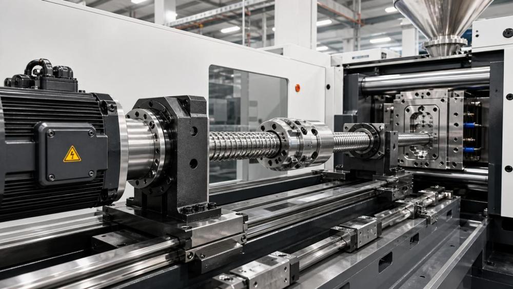
Do not overlook off-axis loading. Ball screws are intended to transmit axial force; they should not compensate for poor guideway alignment, a skewed moving platen, a distorted mounting face, or belt side load. These conditions can introduce bending and uneven ball contact that is not obvious in a basic axial load calculation. A larger screw may mask the symptom temporarily, but it does not correct the installation problem.
Lead selection is a trade-off, not a simple speed upgrade
Lead determines the linear travel per screw revolution. A larger lead gives more axis travel at a given motor speed, which can be attractive when cycle time is under pressure. It also reduces the torque multiplication available from the screw. For the same axial thrust, a higher-lead screw generally requires more drive torque.
Choosing the highest possible lead can therefore create a chain of compromises: a larger motor, more demanding acceleration control, greater sensitivity to inertia, and a higher chance of operating near critical speed. A very low lead has its own limitations. It may force the motor to run at high speed for a modest linear velocity, increase rotation count over a given stroke, and restrict cycle performance.
The better choice comes from checking motor torque-speed capability, screw rpm, reflected inertia, required positioning increment, and process force together. If a candidate lead meets travel speed but leaves the servo with little torque reserve during injection or deceleration, it is not a robust choice. Likewise, if a low-lead design meets thrust but drives the screw close to a speed limit during rapid movement, it deserves further review.
Critical speed and buckling should be checked separately
These two limits are regularly confused because both relate to screw length. Critical speed is a rotational stability issue. As a long screw turns faster, it can approach a natural frequency and begin to whip. Buckling is an axial compression issue: a slender screw can become unstable under compressive load. A design can be safe against buckling yet still be unsuitable at the required rpm, or it can have acceptable speed capacity but insufficient compression margin.
End support condition has a major effect on both calculations. Fixed-fixed, fixed-supported, fixed-free, and supported-supported arrangements behave differently. The bearing blocks, housing stiffness, mounting geometry, and real effective unsupported length must match the assumed configuration. A drawing may show a supported end, but a compliant bracket or loose bearing arrangement can behave less rigidly in service than the calculation assumes.
For long injection or platen strokes, check the maximum rotational speed at the highest commanded linear velocity, not merely the nominal cycle speed. Include overshoot, tuning allowances, and any future program changes that may increase rapid movement. Then check buckling under the most severe compressive process condition, using the actual end condition and a suitable margin. If either limit becomes restrictive, alternatives may include a larger root diameter, a revised lead, a shorter unsupported length, a changed support layout, or a different drive architecture.
Repeatability depends on more than nominal backlash
When molded parts show position-related variation, it is tempting to ask for “zero backlash.” That phrase is incomplete. Repeatability is affected by ball nut preload, screw and bearing stiffness, mount rigidity, coupling behavior, guideway compliance, servo control, temperature, and the direction from which the axis approaches its final position.
A preloaded nut can reduce lost motion and improve response under reversing load, but greater preload also raises friction, heat generation, and required drive torque. Excessive preload is not a free accuracy upgrade. In a high-duty injection axis, it can shorten lubrication intervals and make thermal behavior harder to manage. The appropriate preload level should reflect required positioning repeatability, load reversal, stiffness demand, duty cycle, and the machine’s ability to remove heat.
Rigidity needs to be considered as a system. Under changing injection force, elastic deflection can come from the screw shaft, nut, thrust bearings, bearing seats, motor bracket, coupling, and structure supporting the injection unit. If process control depends on small position changes near the end of injection, evaluate deflection at the relevant force rather than relying only on catalog accuracy grade. A highly accurate screw installed in a flexible assembly cannot deliver the same result as it can in a rigid, aligned structure.
Heat growth can quietly shift the process window
During repeated high-speed operation, friction in the nut and support bearings generates heat. The screw shaft may also receive heat from the surrounding machine or material-processing zone. As the shaft temperature changes, its length changes. That growth can shift a reference position even when the encoder and controller are functioning correctly.
This is why a machine can seem repeatable at startup and drift after sustained operation. The drift may be gradual enough that it is mistaken for random control instability. Look at the timing: Does the deviation develop after a period of fast cycling? Does it change after a long idle interval? Does it differ between cold and warm machine conditions? These observations help distinguish thermal behavior from abrupt mechanical wear or electrical feedback problems.
Possible responses include selecting an appropriate screw diameter and preload, improving lubrication consistency, considering temperature management where the application warrants it, and locating feedback so that the control system can better represent actual table or ram position. The mounting arrangement also matters. A fixed reference at one end and a provision for controlled expansion at the other is often preferable to unintentionally constraining thermal growth through overly rigid support at both ends.
Review the nut, bearings, seals, and lubrication as one assembly
Ball screw assemblies for injection molding machines should be specified with their support bearings and operating environment in mind. The nut style must accommodate the required load, stroke, mounting envelope, and preload target. The support bearings must carry thrust in the intended directions and retain suitable stiffness at operating speed. Couplings need adequate torsional stiffness without transmitting misalignment into the screw.
Contamination deserves attention in molding environments. Fine particles, degraded grease, moisture, and process-related debris can damage raceways even when the screw itself appears protected. Confirm the bellows, covers, wipers, seals, and lubrication delivery arrangement rather than assuming the machine enclosure solves the problem. Lubricant type, delivery interval, and compatibility with the nut and bearing requirements should be defined before commissioning.
For a replacement project, inspect the removed components instead of only copying their part number. Uneven wear, discoloration, pitting, ball track damage, or localized bearing distress may point to alignment, contamination, overload, or lubrication failures. Replacing like-for-like without identifying that cause can repeat the same failure pattern.
A practical comparison method before release
When comparing candidates, request enough information to verify the complete selection: screw diameter and lead, root diameter, nut type and preload, dynamic and static load ratings, permissible speed, critical-speed assumptions, buckling assumptions, end machining details, bearing arrangement, lubrication requirements, and mounting tolerances. A rating without its calculation conditions is difficult to use responsibly.
Then run the intended duty cycle through the proposed assembly. Confirm peak and repeated axial loads, rms torque, maximum rpm, acceleration demand, stroke, reversal frequency, and expected thermal exposure. Review the layout for alignment sensitivity and service access. Finally, compare the predicted behavior with the process requirement: not merely whether the axis can move, but whether it can return, hold, and reverse with the needed stability over normal production time.
The best selection is rarely the largest or highest-rated option in isolation. It is the assembly whose lead, diameter, preload, support method, lubrication approach, and thermal behavior fit the specific motion task. That disciplined comparison reduces the risk of choosing a ball screw that looks adequate on paper but becomes the weak link once injection molding moves from trial cycles to sustained production.
Related News
- How to Assess a Rigid Coupling Supplier for Bore Accuracy and Traceable QualityOct 08, 2026Tribology & Kinematics Expert
- Titanium Alloys Compared: Balancing Strength, Corrosion Resistance, and MachinabilityOct 08, 2026CNC Kinematics Architect
- Where Ductile Iron Dismantling Joints Reduce Alignment Risk in Water PipelinesOct 08, 2026Pipeline Metallurgy Scientist
- Selecting a Precision Bearing Sleeve: Fits, Runout, and Material ChoicesOct 08, 2026Tribology & Kinematics Expert
- Face Milling Cutters: How Insert Geometry Affects Finish on Steel and AluminumOct 08, 2026CNC Kinematics Architect
- Single-Acting Cylinders for Clamping: Stroke, Force, and Return Spring ConsiderationsOct 07, 2026Fluid Power Control Strategist