
Reducing Positioning Errors with Recirculating Ball Guide Linear Motion Systems
Positioning error in a linear axis is rarely caused by one defective component. It is usually the accumulated result of guideway compliance, mounting distortion, preload selection, drive transmission error, structural deflection, thermal movement, and changes in friction over time. A motion system can appear accurate during a short acceptance test yet lose repeatability once it is exposed to varying loads, long travel distances, vibration, contamination, or production duty cycles.
Linear motion systems with recirculating ball guides are often selected because they can provide high load capacity, low and relatively stable rolling resistance, and controlled stiffness within a compact envelope. Those benefits are real, but they only reduce positioning errors when the guide system is treated as part of the full axis design. A high-grade rail cannot compensate for a weak machine base, a misaligned mounting surface, an unsuitable preload, or a servo system tuned around incorrect mechanical assumptions.
The practical objective is not simply to specify the lowest catalog accuracy class. It is to build an axis whose error remains predictable under the loads, speeds, temperatures, and maintenance conditions expected throughout the project life.
Where positioning error enters a linear axis
For a CNC machine, automated assembly cell, coordinate measurement station, or handling system, commanded position and actual tool-center or payload position are separated by an error budget. The guideway is only one contributor, but it has direct influence on several of the most consequential terms.
Guide rail straightness and parallelism affect the path followed by the carriage. Variation in carriage height or lateral position can become pitch, yaw, or roll of the moving member. If the load point is offset from the guide plane—as it is with a spindle, robot end effector, inspection camera, or elevated fixture—small angular changes are amplified into a larger error at the working point.
Guide stiffness matters because an unloaded axis and a working axis are not the same condition. A carriage may return repeatedly to the same encoder position while the payload deflects differently under cutting force, cable drag, changing workpiece mass, or pneumatic and hydraulic reaction loads. This is often interpreted as a control issue even though the source is mechanical compliance.
Friction behavior is another source of error. Sliding guides can deliver high damping, but their breakaway friction and speed-dependent behavior require careful management in low-speed precision applications. Recirculating ball guides reduce friction substantially, which supports smoother motion and lower drive force. Their rolling elements also make the axis more responsive to small disturbances. For this reason, low friction should not be confused with automatic accuracy: structural rigidity and control tuning remain essential.
Finally, guideway condition changes with time. Lubricant degradation, ingress of chips or dust, corrosion, improper wiper contact, and damaged rail surfaces can create local resistance changes. These may appear as intermittent following error, stick-slip-like motion at low speed, higher motor current, noise, or declining repeatability. A positioning strategy that ignores maintenance conditions is incomplete from the outset.
Why recirculating ball guides can improve repeatability
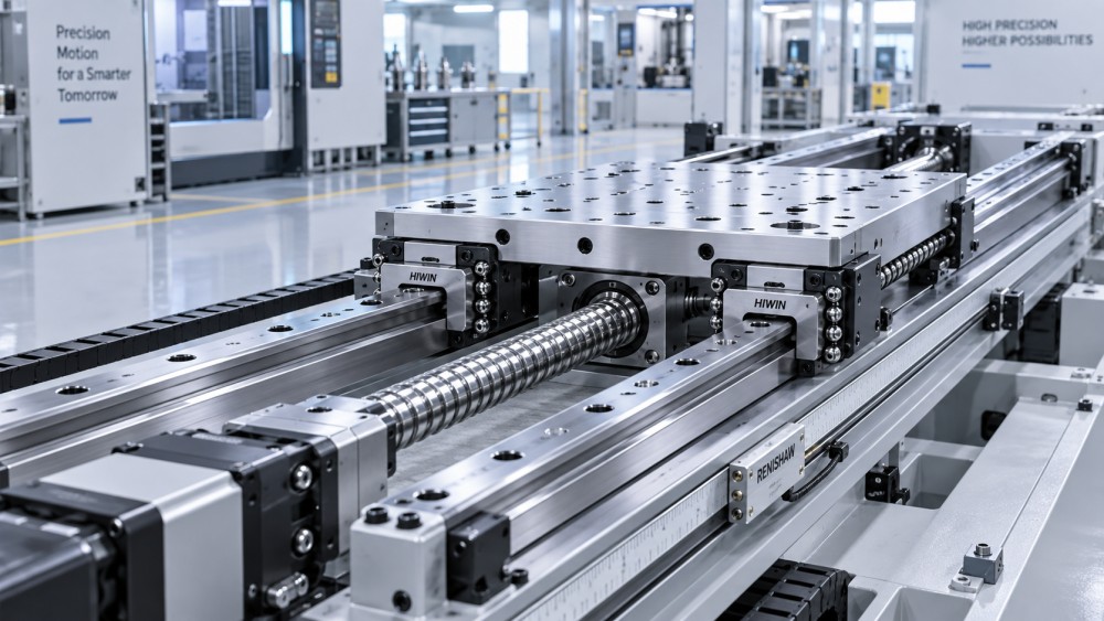
A recirculating ball guide uses rolling elements circulating between the rail and carriage through return paths. Load is transferred through multiple ball contacts rather than through broad sliding contact. The arrangement allows high load capacity and compact carriage dimensions while keeping resistance to motion comparatively low.
The most important positioning benefit is controlled elastic behavior. Under a defined preload and load condition, the carriage responds to external force with a measurable stiffness rather than a loosely constrained clearance. In a properly designed system, this limits unwanted relative movement between the rail and carriage and improves repeatable positioning after direction reversals.
Multi-carriage arrangements add another advantage. Two rails with two or more blocks can establish a wide support base for a moving table or gantry. The spacing between rails and the distance between blocks on each rail determine how effectively the system resists pitch, yaw, and roll moments. Increasing rail size alone may not solve a moment-load problem if the rails remain too close together or the carriage spacing is too short.
These characteristics make recirculating ball guide systems appropriate for many axes requiring repeatable geometric behavior: machining center tables, tool changers, precision transfer units, laser and cutting machine gantries, battery and electronics assembly equipment, inspection stages, and heavy fixture movement. The appropriate arrangement differs sharply between a lightly loaded metrology axis and a machining axis exposed to intermittent cutting loads and coolant contamination.
Preload is a positioning tool, not a default performance upgrade
Preload removes internal clearance by creating an initial elastic interference between rolling elements and raceways. In positioning terms, it improves resistance to small load reversals and helps limit displacement caused by changing forces. It can also raise system natural frequency, which may benefit dynamic behavior where the structure is otherwise sufficiently rigid.
However, excessive preload creates its own risks. It raises rolling resistance, heat generation, and sensitivity to alignment errors. It can reduce travel smoothness if rail mounting surfaces are not sufficiently accurate, and it reduces the margin available for thermal expansion or installation variation. Higher preload also increases the force required from the drive system, which can affect motor sizing, servo tuning, and energy use.
Low preload or clearance may be appropriate where thermal movement is significant, mounting structures are less controlled, long travel is required, or the application prioritizes free movement over tight reversal behavior. Moderate preload is often used where repeatability and stiffness are important but the system must tolerate realistic assembly and operating variation. Heavy preload belongs only where the mechanical structure, installation accuracy, lubrication regime, and load model justify it.
The correct question is not whether preload improves accuracy. It does. The relevant question is whether the entire axis can support the preload level without creating a greater source of error elsewhere. A guide block selected solely for a high preload designation can make a marginal machine frame or poorly machined mounting surface more difficult to control.
Rail geometry and installation determine whether catalog performance is reachable
Recirculating ball guides are precision components, but they follow the geometry presented by the machine structure. If a rail is fastened to a surface with excessive flatness deviation, local waviness, burrs, paint residues, weld distortion, or uneven bolt-seat conditions, the rail is forced into that shape. The carriage then experiences changing internal load as it travels. The symptoms may include uneven running force, localized noise, shortened life, and position variation that is difficult to isolate during commissioning.
Parallelism between rails is equally important in multi-rail systems. A pair of rails that converges, diverges, or varies in elevation imposes parasitic load on the blocks. A system may still move, particularly with lower preload, but its resistance and stiffness will change along the stroke. This directly undermines repeatability at different working positions.
Machined reference shoulders are valuable because they establish repeatable lateral location during installation and replacement. They should not be treated as a substitute for checking the actual assembly. Bolt tightening sequence, torque consistency, and progressive verification of travel force are part of alignment control. On long axes, installation should be checked over the full stroke rather than only at the rail ends.
Where structural machining cannot reliably provide the required rail seat geometry, the project should address that limitation explicitly. Possible measures include redesigning the support structure, using adjustable alignment features, separating the precision rail mounting member from a less accurate welded frame, or selecting a guide arrangement with greater tolerance for the available structure. The correct choice depends on required accuracy, not on a preference for a particular guide type.
Design around the working point, not only the carriage load rating
Catalog load ratings are necessary for life calculations, but positioning performance depends heavily on load location and moment. A vertical spindle carried above the guide plane produces overturning moments during acceleration and cutting. A pallet changer may introduce an offset mass that changes as fixtures are loaded. A camera inspection bridge can remain lightly loaded yet be highly sensitive to angular error because its measurement point is far from the rails.
The design model should therefore include forces and moments at the actual working point: payload weight, acceleration and deceleration, process forces, cable carrier force, pneumatic hose reaction, gravity effects on vertical axes, and foreseeable off-center loading. The resulting reactions at each block should be examined across the operating envelope rather than at one nominal position.
Rail spacing, block spacing, and the height of the moving structure often have greater effect on angular stability than a one-step increase in rail size. Wider rail spacing improves resistance to roll and yaw. Greater longitudinal spacing between blocks improves pitch resistance. Lowering the center of gravity reduces moment demand. In a gantry, torsional stiffness of the crossbeam and synchronization between drives may become more influential than the nominal guide capacity.
A guide system should also be assessed for differential loading during acceleration. An axis that is acceptable at rest may unload one block or concentrate force on another during rapid reversals. That changes elastic displacement and can create position-dependent behavior not visible in static calculations.
The guideway must be coordinated with the drive and feedback architecture
Linear guides constrain motion; they do not establish absolute position. Ball screws, rack-and-pinion drives, linear motors, gearboxes, encoders, and servo controls all contribute to final axis accuracy. A recirculating ball guide can reduce friction and improve mechanical repeatability, but it cannot eliminate screw lead error, backlash in a transmission, encoder scale error, drive compliance, or thermal growth of the machine structure.
This distinction is particularly important when specifying open-loop or semi-closed-loop systems. A rotary encoder on a servo motor reports motor rotation, not necessarily actual table position after screw expansion, coupling compliance, or load-induced deflection. A linear encoder placed close to the controlled working axis provides more direct feedback, but it also requires protection, cable management, and a control strategy that avoids instability caused by flexible mechanics.
Lower guide friction can improve low-speed motion, yet it may reveal poor tuning that was previously masked by higher resistance. Servo tuning should be performed with the intended payload, cable carrier, lubrication state, and motion profile. Tuning an empty table at room temperature and accepting it as representative of production operation creates a predictable commissioning gap.
Thermal behavior deserves the same attention as nominal accuracy
Temperature affects rails, machine beds, ball screws, motors, gearboxes, and the workpiece or inspection artifact. A guide system does not normally generate the largest thermal error on an axis, but preload, lubrication condition, and misalignment can increase rolling resistance and local heat generation. More importantly, a rigidly constrained arrangement can transfer structural thermal movement into the guide blocks.
Long travel systems require a clear thermal expansion concept. This may involve locating one rail as the primary reference and allowing the opposing rail arrangement to accommodate structural variation in a controlled manner, subject to the guide manufacturer’s installation guidance. The support structure must be evaluated as a whole: rails mounted on dissimilar materials or on sections exposed to uneven heat sources can move differently over the travel length.
Warm-up behavior also affects positioning verification. If acceptance testing occurs before the machine reaches representative thermal condition, compensation values and repeatability observations may not reflect production reality. The relevant operating state is the one associated with the actual cycle, spindle duty, ambient environment, and motion intensity.
Lubrication and contamination control are accuracy controls
Lubrication is often discussed as a life requirement, but it also stabilizes motion. Insufficient lubricant increases contact stress and friction variation. Excessive or unsuitable lubricant can create drag, attract contamination, or behave poorly at the operating temperature. The required lubricant type, viscosity, delivery method, and interval should match speed, load, orientation, environment, and manufacturer guidance.
Contamination protection must reflect the actual debris, not a generic clean-versus-dirty classification. Fine abrasive dust, metal chips, coolant mist, weld spatter, process chemicals, and outdoor moisture produce different risks. Standard end seals may be adequate for enclosed dry equipment but insufficient for a machine tool exposed to chips and coolant. Bellows, telescopic covers, scrapers, positive-pressure enclosures, and improved drainage may be necessary where contamination can reach the rail.
Maintenance access is a project design issue. If lubrication ports, inspection points, and covers are difficult to reach after installation, planned maintenance is likely to become deferred maintenance. That increases the chance that a small motion irregularity becomes a rail or block replacement event with alignment and downtime consequences.
Acceptance should test the axis under conditions that matter
A useful commissioning plan separates geometric verification from functional repeatability testing. Rail alignment, straightness, parallelism, mounting bolt condition, and travel force should be checked before control compensation is used to mask mechanical defects. Servo diagnostics should then be reviewed alongside measurements of positioning accuracy, bidirectional repeatability, backlash or reversal behavior, and angular displacement where the application is sensitive to it.
Testing only at the center of travel is inadequate for a long axis. Measurements should cover locations where rail joints, support transitions, cable carrier force changes, or load distribution changes are likely to affect behavior. The moving mass should be representative, and critical tests should be repeated after thermal stabilization.
For systems with strict performance requirements, the project documentation should retain the as-built rail arrangement, preload class, lubrication specification, mounting procedure, measurement method, and baseline results. This creates a practical reference when accuracy changes later and helps distinguish wear, contamination, collision damage, structural movement, and control changes.
Recirculating ball guide linear motion systems reduce positioning error most effectively when they are specified as part of a mechanical accuracy chain. Correct preload, realistic moment-load analysis, controlled rail mounting, coordinated feedback design, thermal management, and maintainable lubrication protect the benefits that rolling guides can provide. The result is not merely smoother travel; it is an axis whose position remains more repeatable and explainable when project conditions become demanding.
Related News
- Using Industrial Air Blow Guns to Clear Chips Without Spreading DebrisOct 15, 2026Fluid Power Control Strategist
- Ductile Iron Pipe Valves: Which AWWA Standards Apply to Water Main Projects?Oct 15, 2026Dr. Elias Vance
- Why Vacuum Suction Cups Lose Grip on MDF in Woodworking MachinesOct 15, 2026CNC Kinematics Architect
- Choosing a Variable Displacement Piston Pump Manufacturer: What to VerifyOct 15, 2026Fluid Power Control Strategist
- Parallel vs. Angular Pneumatic Grippers for Confined Assembly StationsOct 15, 2026Fluid Power Control Strategist
- Die Castings vs. Investment Castings: Which Costs Less at Your Production Volume?Oct 14, 2026Foundry Phase-Change Fellow