
Linear Guide Motion Systems: Selecting Rail Size, Load Rating, and Accuracy Class
Linear Guide Motion Systems: Selecting Rail Size, Load Rating, and Accuracy Class
Selecting linear guide motion systems is a consequential design decision, not a catalog exercise. The rail and carriage assembly may occupy a modest portion of a machine’s bill of materials, yet it directly affects positioning stability, vibration behavior, cycle consistency, maintenance exposure, and the useful life of surrounding components. For project managers, the question is rarely simply whether a guide can carry a stated payload. The more useful question is whether the complete motion axis will remain accurate and reliable under real forces, real installation tolerances, and the intended duty cycle.
This matters across CNC machining centers, robotic transfer units, inspection equipment, packaging lines, industrial presses, material-handling systems, and heavy fabrication machinery. A guide that looks adequate in a static load calculation can still suffer from uneven carriage loading, poor mounting-surface geometry, shock, contamination, or a cantilevered tool head. Conversely, an oversized rail can consume budget and space without correcting a weak frame, unsuitable drive system, or inadequate assembly process.
A sound selection connects rail size, load rating, accuracy class, carriage arrangement, structural stiffness, lubrication, and installation quality. These elements should be reviewed together before a project moves from concept design to sourcing.
Start with the actual motion condition, not nominal payload
The payload shown on a layout drawing is only one input. A linear axis experiences forces generated by acceleration and deceleration, gravity, cutting or process loads, cable drag, seal resistance, and occasional impact. In machining, intermittent cutting forces and spindle-head overhang may govern the selection more than workpiece mass. In a vertical handling axis, braking, emergency-stop conditions, and loss-of-power scenarios deserve close attention. In a hydraulic or pneumatic machine, rapid pressure changes can create transient forces that are not represented by the normal operating load.
Project teams should identify the moving mass, travel length, target speed, acceleration profile, orientation, center of gravity, and expected operating hours. They should also document external loads at their point of application. A load applied far above the rail plane is especially important because it creates a moment. Linear guides are often damaged not by excessive vertical load alone, but by rolling, pitching, or yawing moments that concentrate force on one carriage or one row of rolling elements.
The position of the center of gravity changes during some operations. A telescoping arm, a moving fixture, a pipe-handling attachment, or a robot end effector can alter the load distribution across the stroke. Calculations should therefore evaluate unfavorable positions rather than rely on a single centered condition. If the axis carries a variable product, fixture, or tooling package, the maximum and minimum operating conditions both matter; preload and friction behavior may become less predictable at the low end, while life and stiffness may be challenged at the high end.
Rail size is a stiffness and integration decision
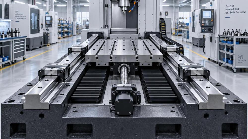
Rail size is commonly discussed as if it were a direct proxy for load capacity. It is not that simple. Larger rail profiles generally offer greater contact capacity and stiffness, but the resulting axis performance depends on the rail spacing, carriage length, number of carriages, base structure, mounting fasteners, and the rigidity of the moving table. Two narrower rails placed farther apart can resist overturning better than a single larger rail arrangement, provided the supporting structure is sufficiently rigid and both rails can be mounted in alignment.
A compact pick-and-place mechanism may prioritize low moving mass and limited installation height. A machine-tool gantry often benefits from wider rail spacing and longer carriage blocks because cutting loads and vibration act at the tool point, not at the bearing center. Heavy-duty industrial equipment may require a rail section selected as much for impact tolerance and mounting robustness as for catalog load rating. For long axes, rail-joint quality, support-frame straightness, and thermal movement can be more influential than selecting the next rail size up.
Do not overlook the interface. Rail mounting surfaces need adequate flatness, straightness, and parallelism for the chosen accuracy class. A high-capacity guide bolted to a flexible welded frame may transfer deformation directly into the carriage. Cast or machined structural members often provide better stability where precision is required, but their machining datum strategy and stress-relief process still need review. In fabricated equipment, localized machining pads, dowel locations, and accessible adjustment features can reduce assembly risk.
Read load ratings correctly: dynamic, static, and moment capacity
Supplier catalogs normally provide a basic dynamic load rating and a basic static load rating. These figures serve different purposes. Dynamic rating is used in bearing-life calculations under repeated motion. Static rating relates to permanent deformation risk when a guide is subjected to high stationary loads, shock, or impact. Neither should be treated as an allowable working load that can be compared casually with the mass of a moving assembly.
The calculation must account for the load carried by each individual block after forces and moments are resolved. An axis with four carriages does not automatically divide its load equally by four. Uneven mounting, structural deflection, rail parallelism error, and a displaced center of gravity can all shift the burden toward a single carriage. This is why the carriage layout should be evaluated early, before the frame geometry becomes fixed.
Moment ratings require the same discipline. Manufacturers may publish permissible moments about different axes, but naming conventions vary. Engineering teams should confirm the supplier’s reference directions rather than assume that pitch, roll, and yaw labels are interchangeable between catalog families. Where combined loading occurs, use the manufacturer’s stated method for calculating equivalent load or safety factors. If the application includes collisions, stamping, rough manual loading, or frequent reversals, the duty conditions should be made explicit in the technical review.
A useful procurement discipline is to ask for the assumptions behind the supplier’s selection statement: load cases, carriage count, rail spacing, assumed load distribution, life target, lubrication method, and environmental correction factors. A recommendation without these assumptions may be difficult to validate when the machine design changes.
Accuracy class should follow the process tolerance chain
Accuracy class is frequently overspecified because it is mistaken for finished machine accuracy. Linear-guide accuracy usually relates to rail dimensional tolerances, running parallelism, height variation, and matching characteristics between rails or blocks. Those properties matter, but the final accuracy at a tool, sensor, or workpiece also depends on ball screw or linear motor behavior, encoder resolution, servo tuning, thermal drift, spindle condition, fixture repeatability, and frame deflection.
For a general material-transfer axis, a standard precision grade may be appropriate if its repeatability requirement is moderate and the structure is tolerant of small deviations. A measuring system, precision grinding machine, or tightly controlled assembly station may require a higher accuracy class, matched rail sets, and a more rigorous alignment process. The key is to trace the required output tolerance backward through the entire system. If an operation requires a certain positional result at the process point, allocate error among the guideway, drive, feedback, structure, tooling, and assembly rather than assigning an arbitrary premium grade to the rail.
Preload deserves similar care. Higher preload can improve stiffness and reduce play, but it also increases friction, heat generation, drive demand, and sensitivity to imperfect mounting geometry. It is not automatically desirable for a long, high-speed axis or an environment with temperature variation. The most appropriate preload is the one that supports the required rigidity without imposing avoidable friction or assembly stress.
Installation quality can erase a good component choice
Many field problems attributed to the guide itself begin at installation. Burrs beneath a rail, paint on a mounting pad, trapped chips, uneven screw tightening, or a distorted machine base can cause preload variation and abnormal running resistance. Parallel rails must be aligned using a defined datum and a repeatable assembly sequence. For high-accuracy or long-travel systems, the manufacturing team should establish how straightness is measured, how rail joints are handled, and how the moving table is checked across the full stroke.
Lubrication is equally practical. The correct lubricant type, delivery interval, and access point should be determined before guards and cable carriers make maintenance difficult. In dusty machining, foundry, mining, or outdoor infrastructure environments, wipers, end seals, bellows, covers, and corrosion-resistant options may be necessary. Protection should be selected according to the actual contaminant: fine abrasive dust, coolant, washdown fluid, metal chips, and salt-laden air create different risks. Sealing cannot compensate for a guideway that is directly exposed to heavy chip impact or persistent water ingress.
A decision package that survives design review
For project leaders, the most reliable selection output is not a part number alone. It is a concise technical package that identifies the axis layout, rail and carriage configuration, load cases, moment directions, life assumptions, accuracy requirement, preload condition, mounting tolerances, lubrication plan, environmental protection, and inspection requirements. It should also state any open items, such as uncertain process forces or pending frame-deflection analysis.
This approach is especially valuable where linear motion interacts with machined frames, forged shafts, gearboxes, hydraulic actuators, or pneumatic handling equipment. IMPE’s coverage of machining capability, power transmission, fluid power, and heavy industrial components reflects a basic project reality: motion performance is created by an assembly of interfaces, not by one premium component. A well-specified guideway can only perform as intended when its structure, drive, sealing, and maintenance plan support it.
Before release, confirm the supplier’s dimensional drawings, catalog definitions, calculation method, matched-set availability, delivery format for long rails, and documentation needed for acceptance. That final review is often where a seemingly straightforward linear guide selection becomes a dependable motion system rather than a future alignment and downtime problem.
Related News
- How to Assess a Rigid Coupling Supplier for Bore Accuracy and Traceable QualityOct 08, 2026Tribology & Kinematics Expert
- Titanium Alloys Compared: Balancing Strength, Corrosion Resistance, and MachinabilityOct 08, 2026CNC Kinematics Architect
- Where Ductile Iron Dismantling Joints Reduce Alignment Risk in Water PipelinesOct 08, 2026Pipeline Metallurgy Scientist
- Selecting a Precision Bearing Sleeve: Fits, Runout, and Material ChoicesOct 08, 2026Tribology & Kinematics Expert
- Face Milling Cutters: How Insert Geometry Affects Finish on Steel and AluminumOct 08, 2026CNC Kinematics Architect
- Single-Acting Cylinders for Clamping: Stroke, Force, and Return Spring ConsiderationsOct 07, 2026Fluid Power Control Strategist