
How to Specify Rolled Ball Screw Assemblies for Speed, Load, and Positioning Accuracy
A linear axis can look straightforward on a layout drawing: a motor, a coupling, a screw, a nut, and a carriage. In operation, however, the screw assembly often becomes the point where competing demands meet. A packaging machine may need rapid indexing; an inspection station may need repeatable positioning; a vertical actuator may carry a changing gravity load; a machine builder may need all three within a controlled cost and lead-time window.
That is why specifying rolled ball screw assemblies requires more than choosing a nominal diameter and lead. Technical evaluators need to translate motion requirements into a balanced selection of speed capability, axial load capacity, positioning accuracy, backlash, stiffness, support arrangement, lubrication, and expected life. The objective is not to select the “largest” or “most accurate” screw. It is to select an assembly whose limitations are understood and whose performance remains stable in the real machine environment.
Start with the motion profile, not the catalog table
A ball screw is usually selected after someone has already defined a target travel speed and payload. Those inputs matter, but they are incomplete. Before comparing catalog options, document the duty cycle in operational terms:
- Required stroke and usable travel
- Maximum linear speed and acceleration
- Moving mass, process force, and external axial loads
- Horizontal, vertical, or inclined installation
- Positioning tolerance, repeatability requirement, and settling time
- Number of cycles per hour, daily operating hours, and design life
- Ambient contamination, temperature range, and lubrication access
This information reveals whether the application is dominated by speed, force, precision, or durability. An axis that moves a light pick-and-place head at high frequency creates a different engineering problem from a slow hydraulic valve actuator or a heavy machine-tool table. In both cases, a rolled screw may be appropriate, but the lead, diameter, preload, bearing supports, and nut type may be very different.
It is also important to distinguish between peak requirements and continuous requirements. A short acceleration burst may create the highest motor torque and axial force, while a long dwell under load may be more relevant to static safety, nut stiffness, or vertical-axis holding behavior. Treating every operating point as a constant maximum condition can lead to an oversized, costly assembly. Ignoring transient peaks can cause early wear, vibration, or loss of position.
Lead converts rotational speed into linear speed
The basic relationship is simple:
Linear speed = screw lead × screw rotational speed
If an axis must travel quickly, increasing lead allows the same linear speed at lower screw rpm. This is often attractive because lower rpm can reduce noise and move the operating point away from critical speed. Yet a higher lead also reduces the mechanical advantage of the screw. More motor torque is needed to generate a given axial force, and the system can become more back-drivable.
For a vertical axis, that trade-off deserves special attention. A high-lead screw may improve cycle time, but it does not automatically provide a safe holding function when power is removed. Brake selection, counterbalance strategy, servo tuning, and safety requirements must be reviewed separately. The ball screw should not be assumed to act as a self-locking device.
Lower-lead rolled ball screw assemblies provide greater thrust per unit of motor torque and can offer finer command resolution for a given encoder count. They are often suitable for feed mechanisms, adjustment axes, and applications where force control matters more than rapid traverse. The practical choice is usually a compromise: select the lead that keeps motor speed, torque, reflected inertia, and control response within acceptable ranges over the complete motion profile.
Check critical speed before treating the speed target as achievable
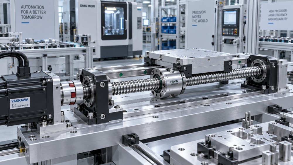
Every rotating screw has a natural bending frequency. As rpm approaches that frequency, the shaft can whip, generate vibration, produce noise, or suffer damage. Critical speed is strongly affected by unsupported length, root diameter, end-support configuration, and installation quality. A screw supported fixed at both ends can operate at a much higher speed than the same screw installed fixed-free.
Catalog critical-speed values should be treated as design guidance, not as permission to run indefinitely at the limit. A reasonable margin is needed for manufacturing variation, mounting alignment, temperature effects, and changes in operating conditions. Long-stroke axes deserve particular caution: increasing diameter may help, but changing the support arrangement, reducing required rpm through lead selection, or considering a rotating-nut architecture may be the more effective answer.
Axial load is more than payload weight
The load seen by a ball screw nut is the combined axial force generated by the application. It may include the moving mass multiplied by acceleration, cutting or pressing force, gravity, seal drag, guideway friction, belt tension effects, and external process loads. On a vertical axis, gravity acts continuously in one direction, while acceleration may add to or subtract from that force depending on the move direction.
Two rating concepts are especially important. The dynamic load rating is used in service-life calculations under repeated motion. The static load rating relates to resistance against permanent raceway deformation when the screw is stationary or experiences shock. A screw can have adequate calculated fatigue life yet still be vulnerable to a crash stop, clamping event, or transported-load impact if static capacity has not been checked.
For life calculations, the equivalent load must reflect the actual duty cycle rather than a convenient single number. Different loads, speeds, and travel distances may need to be weighted according to the manufacturer’s calculation method. In many industrial axes, contamination, poor lubrication, mounting misalignment, and unexpected overload reduce real service life more severely than the nominal load calculation suggests.
Do not overlook buckling on compression-loaded screws. Long, slender screws can become unstable before the nut reaches its published load rating. Buckling risk depends on effective unsupported length and end conditions, much like critical speed. A screw that is safe in tension is not automatically safe in compression.
Accuracy has several layers, and they should not be confused
When a specification says an axis must be “accurate,” it can mean several different things. Lead accuracy describes how closely actual travel follows the nominal lead over a specified length. Repeatability describes how consistently the axis returns to a position. Backlash is lost motion when direction reverses. Positioning error is the accumulated difference between commanded and actual location, influenced by the screw, bearings, nut, coupling, structure, encoder feedback, temperature, and control system.
Rolled ball screws are produced by forming the thread profile rather than grinding it. They are widely used where good motion quality, economical production, and robust general-purpose performance are required. Their lead-accuracy classes and tolerances vary by manufacturer and product series. Technical teams should therefore ask for the applicable accuracy designation, the measurement length, and the stated travel deviation—not simply request a “precision screw.”
A higher screw accuracy class may be necessary for an open-loop positioning axis, a long travel axis without external feedback, or a machine where geometric compensation is impractical. In a closed-loop servo system with a linear scale, however, the encoder can correct much of the lead-related positioning error. That does not eliminate the need for a sound screw assembly. Mechanical backlash, local stiffness variation, thermal growth, and friction still affect settling behavior and process quality.
Preload improves response, but it is not free
Preloaded nuts reduce or eliminate axial clearance by applying internal contact load to the balls. This improves reversal behavior and axial stiffness, which is valuable in contouring, inspection, dispensing, and other direction-changing motions. The cost is increased friction torque, heat generation, and often reduced calculated life. A heavily preloaded assembly may feel reassuring in a static check yet perform poorly during long, high-speed cycles if thermal growth and lubricant condition are not controlled.
For many automation axes, a light preload or controlled axial play is a better fit than maximum stiffness. The correct choice depends on allowable reversal error, process force, required servo bandwidth, and the machine’s thermal environment. Specify backlash and preload in measurable terms where possible, then verify them at assembly acceptance.
Stiffness is a system property
Even an accurately manufactured ball screw cannot make a flexible machine rigid. Total axial compliance comes from the screw shaft, ball nut, bearing blocks, support housing, carriage, linear guides, mounting interfaces, and machine frame. In a high-force pressing or machining application, the frame and bearing supports may contribute more deflection than the screw itself.
End supports are particularly influential. A fixed bearing arrangement generally uses preloaded angular-contact bearings to locate the screw axially. The opposite end may be supported or left free, depending on length, speed, and thermal expansion strategy. Over-constraining the screw can create unwanted axial stress as temperature changes; under-supporting it can limit speed and stiffness. The end machining, bearing seats, locking method, and concentricity should be reviewed as part of the assembly, not treated as incidental details.
Couplings also deserve a practical check. A flexible coupling can accommodate small alignment errors, but it should not be used to excuse poor mounting geometry. Excessive misalignment introduces cyclic loads, vibration, and uneven nut loading. The motor, screw, guides, and carriage should be aligned through a controlled assembly process.
Thermal behavior can quietly consume positioning margin
Steel screws expand as temperature rises. On long axes, even a modest temperature change can create measurable travel variation. Heat may come from nut preload, high rotational speed, bearing friction, nearby process equipment, or changing ambient conditions. In a machine that runs one short cycle per minute, this may be insignificant. In a high-duty automated cell, it can become a recurring source of drift.
Possible responses include lower preload, improved lubrication, a more suitable lead and diameter combination, thermal compensation in the controller, external linear feedback, or a support arrangement that permits managed expansion. The best approach depends on whether the application needs absolute accuracy over the full stroke or only repeatable local positioning after warm-up.
Specify the assembly, not only the screw and nut
A procurement description that lists “20 mm rolled ball screw, 5 mm lead” leaves too much open to interpretation. A usable technical specification should identify the complete functional arrangement:
- Nominal diameter, lead, thread direction, and required stroke
- Overall screw length, end machining drawings, and datum references
- Nut style, flange geometry, mounting orientation, and lubrication connection
- Accuracy class and the required travel-deviation criterion
- Backlash or preload requirement at a stated inspection condition
- Dynamic-life target, maximum axial load, and static/shock-load condition
- Maximum rpm, operating duty cycle, and end-support configuration
- Lubricant type, relubrication interval, seals, bellows, or protective covers
- Material, surface treatment, corrosion exposure, and cleanliness requirements
- Inspection records, traceability expectations, and acceptance measurements
For global sourcing, drawings and terminology should be unambiguous. “Fixed end,” “supported end,” “preload,” and “accuracy” can be interpreted differently across suppliers. Reference the supplier’s published definitions and, where relevant, the applicable ball screw standard framework such as ISO 3408. Confirm whether quoted values apply to the screw alone or to the supplied assembly after nut installation and end machining.
A practical review sequence for technical evaluators
Begin with the motion profile and calculate speed, acceleration force, peak thrust, and average operating conditions. Choose provisional diameter and lead combinations, then screen them for critical speed and buckling using the actual support geometry. Evaluate dynamic life and static safety against the duty cycle. Only after those mechanical limits are credible should the team refine accuracy class, backlash, preload, and thermal strategy.
Next, examine the surrounding axis. Are the linear guides capable of handling the moment loads? Is the motor torque sufficient through acceleration and peak process force? Can the support bearings handle speed and preload? Is there clearance for lubrication fittings, seals, and maintenance? A rolled ball screw assembly performs inside a machine system; it should not be approved in isolation.
Finally, plan verification. Check lead deviation across the relevant travel, backlash at the operating preload condition, bearing arrangement, running torque, and smoothness through the full stroke. For demanding equipment, a thermal run-in and repeatability test under representative load can reveal issues that static inspection will miss.
Well-specified rolled ball screw assemblies bring a useful balance of capability and cost to industrial automation, machinery, and positioning equipment. The strongest specifications do not chase a single catalog number. They connect speed, load, stiffness, accuracy, installation, and lifecycle conditions into one coherent decision—giving engineering, procurement, and production teams a much clearer basis for selecting motion components that will remain dependable after the machine leaves the drawing board.
Related News
- How to Assess a Rigid Coupling Supplier for Bore Accuracy and Traceable QualityOct 08, 2026Tribology & Kinematics Expert
- Titanium Alloys Compared: Balancing Strength, Corrosion Resistance, and MachinabilityOct 08, 2026CNC Kinematics Architect
- Where Ductile Iron Dismantling Joints Reduce Alignment Risk in Water PipelinesOct 08, 2026Pipeline Metallurgy Scientist
- Selecting a Precision Bearing Sleeve: Fits, Runout, and Material ChoicesOct 08, 2026Tribology & Kinematics Expert
- Face Milling Cutters: How Insert Geometry Affects Finish on Steel and AluminumOct 08, 2026CNC Kinematics Architect
- Single-Acting Cylinders for Clamping: Stroke, Force, and Return Spring ConsiderationsOct 07, 2026Fluid Power Control Strategist