
How to Specify Heavy Duty Drive Shafts for High-Torque Industrial Equipment
How to Specify Heavy Duty Drive Shafts for High-Torque Industrial Equipment
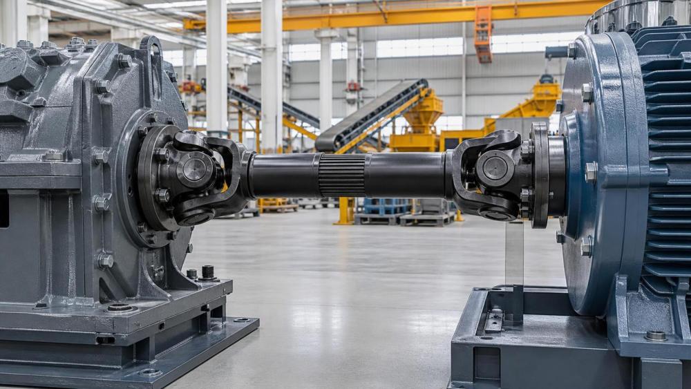
Specifying heavy duty drive shafts begins with understanding the complete operating duty, not simply selecting the largest available shaft diameter or published torque rating.
For project managers, the practical objective is predictable uptime: a drive shaft must transmit required power while tolerating shocks, misalignment, environmental exposure, and maintenance realities.
A correct specification connects equipment loads, installation geometry, material capability, inspection requirements, and supplier documentation before procurement decisions create expensive operational constraints.
This guide explains how project teams can evaluate heavy duty drive shafts for mining, infrastructure, manufacturing, marine, energy, and other demanding industrial applications.
Start With the Actual Torque and Duty Cycle
The rated motor torque is only one input. The shaft must be selected against continuous torque, normal operating torque, transient torque, and credible maximum shock loads.
Calculate transmitted torque from power and rotational speed, then verify whether variable-speed drives, gearbox ratios, braking events, or reversing cycles create higher temporary demand.
Slow-speed applications frequently require larger shafts because torque rises as speed falls. Crushers, mixers, conveyors, presses, and drilling equipment are common examples.
Project teams should obtain a torque-versus-time profile rather than relying on a single nominal value from the equipment data sheet.
Duty cycle matters because repeated loading consumes fatigue life. A shaft that survives occasional overload may still crack prematurely under frequent load reversals.
Document starts per hour, operating hours, direction changes, emergency stops, impact frequency, and expected process jams. These conditions directly influence safety factors and design margins.
High-inertia machinery requires particular attention. Accelerating or stopping flywheels, rotating drums, large pumps, and mill equipment can generate torsional peaks beyond steady-state calculations.
Where uncertainty remains, specify a torque measurement study or require the machinery supplier to provide calculated torsional load cases and assumptions.
Define the Installation Geometry Before Choosing Shaft Size
Heavy duty drive shafts are sensitive to geometry. A suitable torque rating does not compensate for excessive operating angles, incorrect phasing, or inadequate sliding travel.
Universal-joint shafts require carefully managed joint angles. Unequal angles can create nonuniform angular velocity, vibration, bearing loading, and accelerated joint wear.
For double-cardan arrangements, confirm the yokes are correctly phased and the joint angles are balanced wherever the equipment layout allows.
Measure both installed and operating positions. Moving axles, vibrating machinery, thermal expansion, articulated frames, and suspension movement can change shaft length and joint angle.
Specify the required compressed length, extended length, working stroke, and minimum spline engagement. Do not leave telescopic travel as an assumed supplier detail.
A shaft that bottoms out during machine movement can damage gearbox bearings, pump housings, couplings, or universal joints within a short operating period.
Likewise, insufficient spline engagement reduces torque capacity and can cause fretting, spline wear, imbalance, and sudden loss of power transmission.
Provide suppliers with center-to-center distances, shaft offsets, allowable envelope dimensions, connection drawings, and movement ranges for every relevant machine position.
Select Materials and Heat Treatment for Fatigue Resistance
Material selection should address fatigue strength, toughness, hardenability, machinability, corrosion exposure, and repairability. High static strength alone is not sufficient for severe service.
Alloy steels such as 42CrMo4, 4140, 4340, or comparable regional grades are often used where high torsional strength and good toughness are required.
The appropriate grade depends on section thickness, heat-treatment method, notch sensitivity, operating temperature, and the component’s expected loading spectrum.
Forged shaft bodies are often preferred for high-torque equipment because controlled grain flow and reduced internal discontinuities can improve fatigue performance.
Require the supplier to state whether major shaft components are forged, bar-machined, welded, or fabricated, because manufacturing route affects mechanical consistency.
Heat treatment should be specified through target mechanical properties, not only process names. Require tensile strength, yield strength, hardness range, and impact toughness where relevant.
Surface hardening may improve spline or bearing-seat wear resistance, but it must be controlled to avoid brittle surfaces, distortion, or unsuitable hardness transitions.
For critical service, require material certificates, heat numbers, heat-treatment records, and traceability from raw material through final assembly and inspection.
Specify Splines, Flanges, and Joint Connections as Load-Carrying Interfaces
Many drive shaft failures begin at interfaces rather than in the main tube or forged body. Splines, flanges, bolts, and yokes need equal engineering attention.
Sliding spline sections must transmit torque while allowing axial movement. Their design should consider contact length, tooth profile, lubrication method, sealing, and wear allowance.
Choose involute, parallel-sided, or proprietary spline profiles based on equipment requirements and available replacement support, rather than selecting solely by familiarity.
For flange connections, specify pilot diameter, bolt circle, bolt grade, torque procedure, flange thickness, runout limits, and mating-component material requirements.
A piloted flange helps center the joint and reduces reliance on bolts for shear location. This can improve repeatability during installation and maintenance.
Confirm whether the connection will see torsional reversal, axial force, bending moment, or vibration. These combined loads can loosen bolts or deform mating surfaces.
Universal-joint selection should include bearing size, cross design, seal configuration, grease access, allowable angle, and maximum speed at the proposed operating angle.
When specifying proprietary joint series, ensure spare parts remain available in target regions. A technically acceptable shaft creates risk if replacement crosses are unavailable.
Control Critical Speed, Balance, and Torsional Vibration
A heavy duty drive shaft must operate below critical speed with adequate margin. Long shafts can whirl when rotational speed approaches their natural bending frequency.
Critical-speed review becomes increasingly important when shafts are long, small in diameter, mounted on flexible supports, or connected to high-speed motors and gearboxes.
Ask suppliers to calculate critical speed using actual tube dimensions, span, support stiffness, joint mass, and operating configuration rather than generic catalog assumptions.
Dynamic balancing requirements should be defined according to shaft speed, length, rotating mass, machine sensitivity, and applicable industry practice.
Balance quality is especially important for pumps, compressors, high-speed conveyors, test rigs, and equipment installed near personnel or precision instrumentation.
Torsional vibration is different from shaft whirling. It results from oscillating twist caused by cyclic torque, drivetrain inertia, gear mesh behavior, or resonant operating speeds.
Where equipment includes engines, reciprocating compressors, crushers, rolling mills, or variable-frequency drives, consider a torsional vibration analysis during detailed engineering.
A vibration study costs far less than redesigning a shaft, gearbox, or foundation after commissioning reveals unacceptable noise, heat, or repeated component failures.
Address Misalignment, Environmental Exposure, and Maintenance Access
Industrial operating conditions often determine service life more strongly than calculated torque. Contamination, water, heat, corrosion, and poor lubrication can shorten component life dramatically.
For mining, quarrying, and construction equipment, use robust sealing and accessible grease points to protect universal joints and sliding splines from abrasive contamination.
For marine, coastal, wastewater, and chemical environments, evaluate coatings, corrosion-resistant materials, protective boots, and drainage arrangements around rotating assemblies.
Temperature limits should cover both ambient conditions and heat transmitted from nearby engines, furnaces, gearboxes, or process equipment.
Lubrication requirements must match the maintenance organization. A shaft requiring frequent manual greasing is unsuitable where safe access is limited or maintenance intervals are long.
Specify grease type, lubrication interval, automatic lubrication compatibility, and service-point orientation. Grease fittings should remain accessible after guards and piping are installed.
Guarding is also part of the specification. Rotating drive shafts present severe entanglement hazards, particularly in exposed conveyor, pump, and mobile equipment installations.
Require guards that meet site safety rules while still allowing inspection, lubrication, and removal without dismantling unrelated machinery or interrupting major process systems.
Use Standards, Inspection, and Documentation to Reduce Procurement Risk
Standards do not replace engineering judgment, but they create a common language for dimensions, materials, balancing, testing, and acceptance between project teams and suppliers.
Identify applicable ISO, DIN, SAE, ASTM, EN, API, OEM, or customer-specific requirements early. The correct standard depends on equipment type and project location.
For critical heavy duty drive shafts, define an inspection and test plan before purchase order release. It should identify hold points, witnesses, records, and acceptance criteria.
Typical inspection items include dimensional verification, spline measurement, runout checks, magnetic-particle testing, ultrasonic testing, hardness testing, balance reports, and functional rotation checks.
Non-destructive testing should be targeted to risk. Forged yokes, welded assemblies, highly loaded flanges, and shafts with demanding fatigue duty may justify additional examination.
Require certificates of conformity, material test reports, heat-treatment records, coating reports, balance certificates, assembly drawings, and installation instructions in the document package.
For multi-site projects, include part numbers, revision control, interchangeability requirements, preservation methods, packaging details, and recommended spare-part lists in procurement specifications.
Clear documentation prevents field teams from installing an incorrect shaft variant, mating incompatible flanges, or replacing a component with an unverified alternative.
Evaluate Suppliers Beyond Catalog Torque Ratings
Catalog torque ratings are useful screening tools, but project managers should evaluate whether a supplier can manufacture, inspect, support, and repeat the specified configuration.
Request evidence of relevant applications, particularly where shafts operate under high shock, continuous duty, extreme angles, corrosive exposure, or difficult maintenance conditions.
Review manufacturing capability for forging, machining, welding, balancing, heat treatment, and non-destructive testing. Outsourced processes are acceptable only when quality control remains traceable.
Ask how the supplier validates torque capacity, fatigue performance, weld integrity, spline engagement, and universal-joint durability for custom or modified shafts.
Lead time should include engineering review, material availability, prototype approval, testing, and documentation. Urgent replacement needs often expose weak supply-chain planning.
For critical equipment, consider holding strategic spares or specifying interchangeable shaft assemblies across similar machines. This can materially reduce downtime after unexpected damage.
Evaluate lifecycle cost rather than purchase price alone. A lower-cost shaft can become expensive when it requires frequent lubrication, premature replacement, or extended production stoppages.
The best supplier relationship provides responsive technical communication, controlled revisions, reliable delivery, and support when field measurements differ from original design assumptions.
Build a Practical Heavy Duty Drive Shaft Specification
A complete specification should begin with application details: equipment type, transmitted power, speed range, continuous torque, peak torque, shock loads, and duty cycle.
It should then define geometry, including connection types, flange drawings, installed length, extension range, operating angles, allowable envelope, and rotating-direction requirements.
Add material and quality requirements covering shaft construction, steel grade or approved equivalent, heat-treatment properties, hardness, corrosion protection, and traceability expectations.
State performance requirements for allowable speed, critical-speed margin, balance grade, joint angle limits, spline travel, lubrication, sealing, and environmental operating conditions.
Include inspection requirements, applicable standards, required reports, packaging, preservation, installation instructions, warranty terms, and spare-parts recommendations for the intended project lifecycle.
Where the shaft is mission-critical, require supplier engineering approval of the final application data. This assigns responsibility for reviewing the real operating envelope.
Before release, compare the proposed shaft against the machine layout and maintenance plan. Confirm guards, grease access, removal space, lifting provisions, and replacement logistics.
This final review often identifies practical conflicts that calculations alone cannot reveal, especially on retrofit projects or crowded industrial installations.
Conclusion
Reliable heavy duty drive shafts are specified through a disciplined review of torque, fatigue duty, geometry, materials, connections, vibration, maintenance, and supplier capability.
Project managers should treat the drive shaft as a critical drivetrain assembly rather than a commodity component selected only by diameter and nominal torque.
When requirements are documented early, teams reduce commissioning delays, avoid premature failures, improve spare-part readiness, and protect the long-term availability of high-torque equipment.
The strongest procurement decision combines verified engineering data with practical site conditions, quality documentation, and a supplier capable of supporting the shaft throughout its service life.
Related News
- Using Industrial Air Blow Guns to Clear Chips Without Spreading DebrisOct 15, 2026Fluid Power Control Strategist
- Ductile Iron Pipe Valves: Which AWWA Standards Apply to Water Main Projects?Oct 15, 2026Dr. Elias Vance
- Why Vacuum Suction Cups Lose Grip on MDF in Woodworking MachinesOct 15, 2026CNC Kinematics Architect
- Choosing a Variable Displacement Piston Pump Manufacturer: What to VerifyOct 15, 2026Fluid Power Control Strategist
- Parallel vs. Angular Pneumatic Grippers for Confined Assembly StationsOct 15, 2026Fluid Power Control Strategist
- Die Castings vs. Investment Castings: Which Costs Less at Your Production Volume?Oct 14, 2026Foundry Phase-Change Fellow