
Choosing a Linear Motion System Supplier for High-Load Automation Projects
The lowest quoted price for a high-load linear motion assembly often produces the highest installed cost when the rail, carriage, drive, mounting structure, and maintenance plan were evaluated separately. A system that fits the nominal payload but develops carriage preload loss, rail indentation, positioning drift, or lubrication starvation under real duty will consume time in alignment, replacement parts, and unplanned shutdowns. Supplier selection should begin with the actual load spectrum and machine geometry, then test whether the proposed arrangement has enough margin for the full operating condition.
High-load automation commonly combines vertical forces, offset centers of gravity, acceleration, deceleration, vibration, and moment loads. A catalog load rating is useful, but it is only one input. The useful comparison is the supplier's documented calculation for the intended rail spacing, carriage count, mounting orientation, stroke, speed profile, and expected service environment. A quote based on a static mass alone leaves too much unresolved.
Start with the load case, not the rail size
A linear guide carries forces through rolling elements and raceways, but the damaging condition is frequently a moment rather than the direct vertical load. A heavy fixture placed far from the carriage centerline creates pitching, rolling, or yawing moments. During rapid travel, inertial force acts through the moving mass center and can reverse direction at each change in motion. On a vertical axis, a brake event or loss of drive torque introduces another load state that may be more severe than ordinary travel.
Request that each proposed system be evaluated against all relevant states: stationary holding, peak acceleration, deceleration, emergency stop, tool or pallet change, maintenance position, and any process force transmitted into the moving member. For a machining or pressing operation, cutting or forming force may enter at a changing location. For a handling axis, the payload may be centered during transport but eccentric during pick or release. These distinctions change carriage loading substantially.
It is also necessary to separate the calculated applied load from the rated values used by the linear motion system supplier. Dynamic load rating relates to rolling fatigue life under a defined calculation method; static load rating addresses permanent deformation risk under high stationary or shock loading. Neither rating by itself confirms that the assembly will meet stiffness, deflection, accuracy, or contamination requirements. A rail can be adequate for calculated life yet allow enough elastic movement to affect a vision process, weld path, seal compression, or tool engagement.
Moment capacity is easy to overstate
Suppliers may show permitted moments for an individual carriage, while the installed system uses two rails with several carriages and a particular spacing. Those published values cannot always be multiplied directly. Load distribution depends on the flatness of the mounting surfaces, structural rigidity, preload variation, rail parallelism, and how the load enters the moving plate. A stiff welded frame and a thin fabricated plate can use the same guide hardware but generate very different carriage sharing.
Ask for the assumed distribution model and the factors applied for unequal sharing. Where loads are high or cycle rates are demanding, require a drawing that shows rail centers, carriage locations, force application points, and calculated reactions at each carriage. This turns a broad capacity claim into a reviewable engineering basis.
Compare complete motion architectures
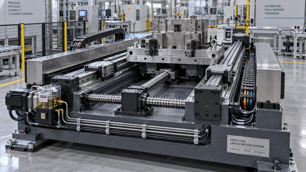
The guideway is only part of the motion system. A rail-and-carriage arrangement combined with a ballscrew, rack and pinion, belt drive, linear motor, hydraulic cylinder, or pneumatic actuator has different limits for force transmission, positioning, backdriving, and service. The same payload can call for a different design when stroke length, duty cycle, stopping precision, and external process loads change.
A ballscrew offers controlled linear positioning and high thrust within a practical stroke range, but screw critical speed, buckling, support bearing selection, and thermal growth must be reviewed. Long screws can require larger diameters or changed drive arrangements to preserve speed and stiffness. Rack drives suit long travel and high-force applications, yet gear quality, pinion preload, gearbox backlash, lubrication, and rack joint alignment become part of the accuracy and maintenance discussion.
Hydraulic actuation can be appropriate where large force and rugged service dominate, but seal condition, fluid cleanliness, temperature, valve response, and load-holding behavior need to match the process requirement. Pneumatic actuation remains useful for simpler end-to-end motion, although air compressibility makes it a poor substitute where controlled position under changing heavy loads is required. A supplier that quotes only guide rails while excluding the interaction with the drive leaves the most consequential interface unexamined.
Accuracy claims need a machine-level interpretation
Positioning accuracy, repeatability, straightness, parallelism, and backlash describe different behaviors. Repeatability indicates how consistently an axis returns to a commanded position under stated conditions. It does not establish absolute position over a long stroke. Rail straightness does not correct a base that is bowed after welding or distorted by bolting. A high-resolution encoder cannot compensate for structural compliance under a changing process load unless the control arrangement measures and corrects the relevant error.
For high-load work, stiffness and settling behavior often deserve as much attention as nominal accuracy. An axis may arrive at the commanded coordinate rapidly but oscillate before the load settles. That response affects dispensing, inspection, cutting, insertion, and other operations where the process starts immediately after motion ends. Ask for the assumptions behind accuracy values: measurement length, temperature, mounting condition, preload class, drive type, and whether the value applies to the guide component or the assembled axis.
Preload selection requires the same care. Greater preload can improve rigidity and reduce internal clearance, but it raises running resistance and can increase sensitivity to installation error. Excessive preload on a long axis with marginal base flatness may produce uneven travel force and localized wear. For a heavily loaded but slow-moving machine, the preferred arrangement may differ from one that accelerates continuously at high cycle frequency.
Examine the material and manufacturing evidence
High-load linear guides depend on raceway hardness, rolling-element quality, surface finish, sealing, and the consistency of heat treatment. The useful question is not whether a rail is described as hardened steel, but whether material identity, hardness treatment, grinding quality, and inspection records can be tied to the supplied lot when the application requires that level of traceability. This matters where replacement rails must match an existing setup or where a failure investigation would otherwise have no reliable material record.
The mounting interfaces deserve equal attention. A precision guide mounted on an unmachined or poorly relieved fabricated surface inherits the errors of that surface. Welded structures can retain stress that changes after machining, transport, or temperature cycling. Cast machine beds offer damping and stiffness advantages in some layouts, but their machined rail pads, threaded holes, and local wall thickness must still support the clamp load without distortion. The supplier's installation drawings should state required flatness, parallelism, shoulder geometry, fastener size, tightening sequence, and datum surfaces.
Surface protection should match the environment rather than serve as a generic upgrade. Coolant, washdown fluids, abrasive dust, welding fume, metal chips, and outdoor moisture create different failure paths. A seal that excludes coarse chips may not protect against fine abrasive slurry. Bellows, telescopic covers, wipers, and positive-pressure arrangements add protection but can increase moving mass, drag, and packaging space. Verify the exposed rail length at full stroke and the way debris is prevented from accumulating at rail ends.
Lubrication and access determine the service burden
A lubrication port visible in a catalog drawing does not guarantee access once the axis is enclosed. Long machines may need distribution lines, metering devices, or centralized lubrication points. Those lines must be routed so they do not flex beyond their limits, interfere with cable carriers, or become damaged during fixture changes. If several carriages share one circuit, the design should account for line length and resistance so the furthest point is not starved.
Grease selection also has consequences. A heavier grease may remain in place under load but increase starting resistance in cold conditions. Oil systems can support frequent replenishment and heat removal in demanding applications, while requiring greater attention to leakage control and containment. Do not accept an unspecified “maintenance-free” description for a high-load axis without understanding the duty assumptions, contamination level, and stated relubrication method.
Wear is not always visible as obvious rail damage. Rising motor current, uneven travel force, worsening vibration, changing repeatability, grease discoloration, or abnormal noise near a particular stroke location can indicate alignment error, contamination, inadequate lubrication, or local overload. The supplier should be able to identify what inspection observations distinguish these causes and which replacement components can be supplied without forcing a complete axis rebuild.
Evaluate the quotation as an engineering deliverable
A usable quotation identifies the precise rail series, carriage configuration, preload, accuracy class, seal option, lubrication arrangement, drive components, motor interface, sensors, cable routing assumptions, protective covers, and mounting hardware. It should also state what is excluded. Ambiguity around base machining, controller tuning, end stops, brake configuration, guarding, or field alignment becomes expensive after orders are released.
Delivery promises should be checked at the assembly level. Rails may be available while matched carriages, machined end plates, long ballscrews, gearboxes, cable carriers, and protective covers have different lead times. Long rails can require special packaging to prevent bending or handling damage. Confirm shipment length, splice arrangements where applicable, lifting provisions, corrosion protection during transit, and the inspection required before installation. A rail damaged in transit can delay an entire build even when the damaged component itself has a modest unit cost.
Technical documentation should support installation and later maintenance, not merely satisfy an order file. Useful records include general arrangement drawings, interface dimensions, load calculations, lubrication instructions, tightening requirements, electrical and pneumatic schematics where relevant, component identification, inspection data, and spare-part references. When an axis is custom-built, establish whether future replacements require original configuration data, whether equivalent components can be substituted, and how revisions will be controlled.
Use total installed cost as the comparison frame
Price comparison is valid only after scope, performance assumptions, and support obligations are aligned. Include base preparation, machining of datum surfaces, assembly labor, controls integration, guarding, commissioning time, lubrication equipment, spare carriage availability, shipment handling, and planned service access. A lower-cost component set may require tighter site alignment or more frequent intervention than an integrated assembly, shifting cost into the machine build and operational schedule.
Before release, reconcile the final supplier calculation with the approved machine drawing and motion profile. Changes that appear minor, such as a heavier end effector, a wider fixture, a faster acceleration setting, or relocation of a cable carrier, alter moments and drive demand. Treating those revisions as configuration changes rather than informal adjustments preserves the basis on which guide life, stiffness, and positioning behavior were selected.
The strongest selection is supported by a clear chain from real load conditions to component arrangement, mounting design, protection, maintenance access, and documented delivery scope. That chain is what converts a quoted linear motion system into a dependable high-load machine axis.
Related News
- Using Industrial Air Blow Guns to Clear Chips Without Spreading DebrisOct 15, 2026Fluid Power Control Strategist
- Ductile Iron Pipe Valves: Which AWWA Standards Apply to Water Main Projects?Oct 15, 2026Dr. Elias Vance
- Why Vacuum Suction Cups Lose Grip on MDF in Woodworking MachinesOct 15, 2026CNC Kinematics Architect
- Choosing a Variable Displacement Piston Pump Manufacturer: What to VerifyOct 15, 2026Fluid Power Control Strategist
- Parallel vs. Angular Pneumatic Grippers for Confined Assembly StationsOct 15, 2026Fluid Power Control Strategist
- Die Castings vs. Investment Castings: Which Costs Less at Your Production Volume?Oct 14, 2026Foundry Phase-Change Fellow