
Acme Lead Screws: Selecting Pitch, Material, and Nut Design for Linear Motion
A linear axis can appear straightforward on a drawing: a motor turns, a nut travels, and the carriage reaches position. Problems usually emerge after the assembly is asked to move a real load repeatedly. A fast-traveling nut may run hot, a heavy vertical load may creep backward when power is removed, or a positioning mechanism may show more lost motion than the machine can tolerate. In these situations, the lead screw is rarely selected correctly by diameter alone.
For most industrial applications, the right approach is to select acme lead screws by starting with required linear speed and load, then checking whether the chosen pitch creates acceptable torque, self-locking behavior, critical speed, and wear rate. Material and nut design should be chosen around the operating environment, duty cycle, lubrication access, and allowable backlash. A coarse pitch is not automatically better for speed, and a harder screw is not automatically the best wear solution.
Begin with the motion requirement, not the catalog thread size
Acme threads are commonly used where a mechanism needs durable, economical conversion of rotary motion into linear travel. Their trapezoidal thread form has broad contact surfaces compared with ordinary fastening threads, making them suitable for clamps, lifting mechanisms, manual adjustments, valve actuators, press equipment, machine guards, industrial slides, and many custom-built assemblies.
The first selection question is not “Which screw diameter is available?” It is “What must the axis do during its worst operating condition?” Define the following before comparing screw options:
- Maximum axial load, including work load, carriage weight, tooling force, and external process forces.
- Required travel speed and whether movement is continuous, intermittent, or mainly manual.
- Travel length between supports.
- Horizontal, inclined, or vertical mounting orientation.
- Required positioning repeatability and permissible backlash.
- Expected starts, stops, reversals, and dwell time.
- Exposure to dust, chips, washdown, abrasive particles, chemicals, or temperature variation.
- Whether lubrication can be applied and maintained during service.
A screw that performs acceptably in a hand-operated fixture can fail quickly in a motorized axis because rotational speed, duty cycle, and heat generation change the operating conditions. Conversely, specifying a high-cost precision assembly for a slow adjustment device may add expense without improving the real function of the equipment.
Pitch sets a trade-off between speed, torque, and holding behavior
Pitch is the axial distance advanced by the nut in one revolution for a single-start screw. With multi-start threads, the lead is greater than the pitch because the nut advances one lead per revolution. For selection purposes, the lead determines linear travel per revolution and therefore has the most direct effect on speed and required motor speed.
A larger lead produces more travel per revolution. This can reduce the motor rpm needed for a given linear speed, which is useful on longer-stroke equipment or mechanisms that must move promptly between positions. The trade-off is that a larger lead demands more driving torque for the same axial load and is less likely to resist back-driving.
A smaller lead gives a greater mechanical advantage. It can reduce input torque, improve manual control, and make self-locking more achievable under appropriate friction conditions. This is often attractive for jacks, clamps, lifting adjustments, and vertical positioning devices where uncontrolled reverse motion would be unacceptable. However, a fine-lead screw must turn faster to produce the same linear speed. At higher rpm, it may approach critical speed, create more frictional heating, or become impractical for the available drive.
Do not treat self-locking as a guaranteed property of a thread form. It depends on lead angle, friction, lubrication condition, vibration, load direction, wear, and the material pairing. A mechanism that holds reliably when dry and new may back-drive after lubrication changes or after the thread surfaces have worn in. Where a suspended load creates a safety concern, use a dedicated brake, counterbalance, or positive locking arrangement rather than relying only on screw friction.
Multiple starts can be useful when a design needs a larger lead without using an extremely coarse thread profile. They should still be assessed as higher-lead designs: speed improves, but torque demand and back-driving risk must be reconsidered.
Check rotational limits before finalizing pitch
A screw that must rotate rapidly over a long unsupported length is vulnerable to whirling. This occurs when rotational speed approaches the screw’s critical speed, causing vibration, noise, runout, and potentially rapid damage to the nut and support bearings. The usable limit depends on root diameter, unsupported length, end-support arrangement, straightness, and how much operating margin is retained.
End support conditions matter. A screw supported by bearings at both ends has a more favorable critical-speed condition than one with a free end. However, the support arrangement must match the real machine, not an optimistic sketch. Bearing play, flexible mounting plates, poor alignment, and insufficient shaft engagement can reduce the benefit of an apparently rigid design.
Pitch selection should therefore be checked in sequence. Convert the requested linear velocity into screw rpm using the selected lead. Compare that speed with the screw’s critical-speed capability for its actual unsupported length and end conditions. If the speed is too high, possible remedies include a larger screw diameter, a shorter unsupported span, a different support method, a greater lead, a reduced travel-speed requirement, or a different linear-motion technology.
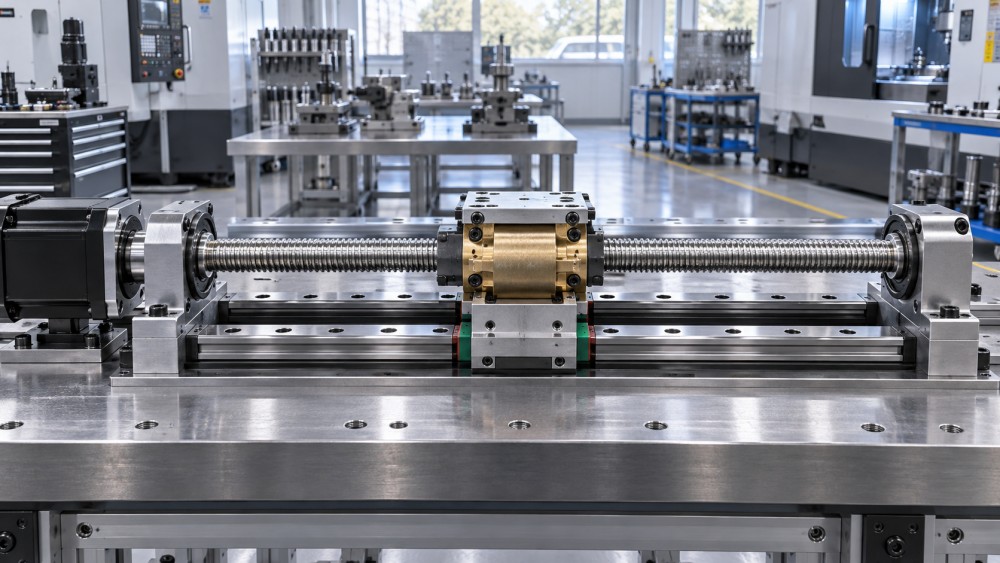
Buckling deserves a separate review when the screw carries compression. A long, slender screw may be safe in tension but unstable in compression, especially where the load is applied near mid-travel and the effective unsupported length is greatest. Diameter, root section, end fixing, load direction, and the location of the moving nut all affect the result. A screw intended for compression should be evaluated at the least favorable position, not only at the parked position near a support.
Material choice is a system decision
The screw material must provide adequate strength, straightness, machinability, surface condition, and compatibility with the nut. Carbon and alloy steels are frequently selected for strength and stiffness. Depending on the service requirement, a steel screw may be supplied with a machined finish, a rolled thread, a protective coating, or a hardened surface. Hardened screws can resist wear, but they need a nut material that will not damage the mating thread or seize when lubrication is poor.
Stainless steel is often considered where corrosion or washdown exposure is a concern. That choice should not stop at corrosion resistance. Some stainless combinations are more prone to galling, particularly under high contact pressure and marginal lubrication. The full screw-and-nut pairing, rather than the screw material by itself, determines whether the assembly will slide smoothly over time.
Surface treatment may improve corrosion resistance, reduce friction, or enhance wear behavior, but it can also change the practical fit between screw and nut. Confirm thread tolerances after coating or treatment, especially where backlash is tightly controlled. A coating that is suitable for an exposed screw may not remain appropriate if abrasive contamination becomes embedded in the nut.
For corrosive, wet, or chemically exposed equipment, ask what contacts the threads during operation. Clean water, cutting fluid, alkaline washdown, salt-containing moisture, and process chemicals create different risks. Shielding, bellows, wipers, drain paths, and lubricant selection may be more effective than upgrading screw material alone.
The nut often determines service life
The nut is the wearing member in many acme screw assemblies, and it should be treated as a functional component rather than an accessory. Nut material governs friction, load distribution, lubrication needs, contamination tolerance, operating temperature, and the way backlash develops during service.
Bronze and metal nuts
Bronze nuts are widely used with steel screws because they provide good bearing properties and can handle substantial loads when correctly sized and lubricated. They are often appropriate for industrial machinery, heavy adjustments, and applications where stiffness matters. Their limitations include sensitivity to poor lubrication, abrasive contamination, and excessive pressure-velocity conditions. A bronze nut that is undersized may wear rapidly even though the screw itself remains visually undamaged.
Metal nuts may also be designed with a flange, cylindrical body, mounting holes, keyways, or custom features for anti-rotation and load transfer. The housing must support the nut without distortion. Clamping a nut body unevenly or forcing it into a misaligned bore can create localized thread loading and shorten life.
Polymer and composite nuts
Engineered polymer or composite nuts can offer low friction, quiet operation, corrosion resistance, and reduced lubrication requirements. They can be useful in light-to-moderate load mechanisms, enclosed equipment, food-adjacent designs where conventional grease is undesirable, or systems that must operate cleanly. Yet “self-lubricating” does not mean unlimited duty. High temperature, sustained load, shock loading, and abrasive particles can accelerate creep or wear.
Confirm the actual load direction and duty cycle before choosing a polymer nut. A light load moving occasionally is different from a light load held in one position for long periods. Long-term static loading can affect clearance and positioning even when the running load seems modest.
Anti-backlash designs
Standard single nuts have unavoidable clearance. That clearance allows free movement before the load reverses direction, which appears as backlash at the carriage. For manual adjustment or one-direction loading, a conventional nut may be acceptable. Reversing axes, inspection fixtures, dispensing mechanisms, and position-sensitive machinery may need an anti-backlash arrangement.
Common approaches use two nut elements preloaded against opposite flanks of the screw thread through a spring, adjustable spacer, or mechanical preload. Preload reduces lost motion, but it also raises friction and heat. Excessive preload can consume motor torque, speed up wear, and make a system bind as temperature changes. The correct target is not zero clearance at all costs; it is repeatable motion within the machine’s required accuracy while preserving reasonable running torque.
Load rating must include pressure, velocity, and duty cycle
Axial load alone is an incomplete basis for nut selection. Thread contact pressure increases as load rises and as effective engagement length decreases. Sliding speed rises with screw rpm and lead. Together, pressure and velocity determine how much frictional heat the nut can tolerate. A design that works at high load and low speed may fail at a lower load if it runs continuously at much higher speed.
Use the worst combination of load, speed, and duty cycle, not isolated maximum values that never occur at the same time. Also consider acceleration, impact at end stops, side loads transmitted from an imperfect guide system, and contamination entering the thread. Lead screws should carry axial load; external linear guides should carry radial load and moments. When the screw is forced to compensate for poor guide alignment, the nut can wear unevenly and the drive torque becomes erratic.
Installation errors can look like material or pitch problems
A newly installed assembly that runs smoothly by hand but binds under power often has an alignment issue. The screw centerline, nut mounting face, guide rails, bearing blocks, and drive coupling must work together. Flexible couplings can accommodate minor shaft misalignment, but they do not correct a nut that is being pulled sideways by the carriage.
During assembly, mount the screw and supports first, verify free rotation, then position the nut and carriage with the guide system aligned. Move the carriage through the full stroke before locking all mounting hardware. Torque should remain reasonably consistent from end to end. A sharp increase at one location can indicate screw runout, damaged threads, rail misalignment, a distorted nut mount, or a support bearing problem.
Protect exposed threads where chips, grinding dust, sand, or welding debris are present. Contaminants can act like abrasive paste between the nut and screw. Wipers and covers are useful only when they are maintained; a damaged wiper that traps debris against the thread may create its own wear path.
Information to request before approving a screw assembly
Before release, confirm the thread designation, pitch or lead, number of starts, handedness, nominal and root dimensions, usable threaded length, total length, end machining, straightness requirement, material, surface condition, nut material, and intended lubrication. Drawings should identify bearing locations, coupling interface, anti-rotation features, and the usable travel envelope so the nut cannot run into an unthreaded section or support shoulder.
Where positioning matters, define backlash in the assembled mechanism rather than assuming a thread designation guarantees a particular result. Where load holding matters, document the brake or locking strategy. Where the assembly is exposed, specify the protection and maintenance expectation. These details prevent a technically correct screw from becoming an unsuitable motion system once it is installed.
Related News
- How to Assess a Rigid Coupling Supplier for Bore Accuracy and Traceable QualityOct 08, 2026Tribology & Kinematics Expert
- Titanium Alloys Compared: Balancing Strength, Corrosion Resistance, and MachinabilityOct 08, 2026CNC Kinematics Architect
- Where Ductile Iron Dismantling Joints Reduce Alignment Risk in Water PipelinesOct 08, 2026Pipeline Metallurgy Scientist
- Selecting a Precision Bearing Sleeve: Fits, Runout, and Material ChoicesOct 08, 2026Tribology & Kinematics Expert
- Face Milling Cutters: How Insert Geometry Affects Finish on Steel and AluminumOct 08, 2026CNC Kinematics Architect
- Single-Acting Cylinders for Clamping: Stroke, Force, and Return Spring ConsiderationsOct 07, 2026Fluid Power Control Strategist