
Socket Weld Pipe Flanges: When Are They the Right Choice for High-Pressure Lines?
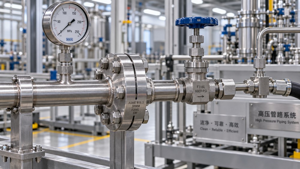
Socket weld pipe flanges are a strong option when a piping system needs a compact, mechanically stable connection for relatively small-bore, high-pressure service—but pressure capability alone does not make them the correct choice. Their real value lies in the combination of socket-based alignment and an external fillet weld. Their principal limitation is equally important: the socket creates an internal crevice that can become a corrosion, contamination, fatigue, or inspection concern depending on the fluid and duty cycle.
The most defensible selection decision is therefore not “high pressure means socket weld.” It is: use a socket weld flange where the design code permits it, the line size and geometry are appropriate, the process medium does not make the socket crevice unacceptable, and the welding and examination plan can control the joint reliably. In many high-pressure utility, hydraulic, steam, and instrumentation-adjacent applications, that combination can be practical. In corrosive, sanitary, cyclic, or piggable systems, a butt-weld neck flange may carry lower lifecycle risk even when its initial fabrication cost is higher.
What the socket weld geometry actually changes
A socket weld flange has a recessed bore that receives the pipe end. The pipe is inserted into the socket, backed off slightly to preserve a root gap, and fillet welded around the outside. This differs from a slip-on flange, where the pipe passes through the flange bore and is typically welded at both the hub and the bore side. It also differs fundamentally from a weld neck flange, which uses a full-penetration butt weld between the pipe and a tapered hub.
The socket provides positive pipe location before welding. That feature can improve fit-up consistency on small pipe sizes and in assemblies where maintaining face orientation matters. The external fillet weld is also accessible from the outside of the joint, which can simplify fabrication relative to configurations requiring access to the flange bore.
However, the pipe end does not become part of a smooth, continuously blended internal bore. A circumferential recess remains at the end of the socket. That discontinuity is the reason socket weld connections need a more selective application review than their compact appearance suggests.
Under the ASME system, socket weld flanges are covered by ASME B16.5, while forged socket-welding fittings are commonly specified to ASME B16.11. The applicable piping code—such as ASME B31.3 for process piping or ASME B31.1 for power piping—controls whether the joint type is permitted in the intended service and how it must be fabricated and examined. Flange dimensional compliance does not, by itself, establish system suitability.
Where socket weld flanges have a practical advantage
The most suitable applications tend to share several characteristics: relatively small nominal pipe size, substantial internal pressure, manageable wall thickness, limited need for internal cleaning, and a process medium that is not especially vulnerable to crevice effects.
For compact small-bore lines, socket weld construction can provide more secure assembly alignment than a slip-on flange. This matters when a flange must be oriented precisely to connect valves, instruments, pumps, compact skids, or prefabricated pipe sections. The pipe is seated against a defined socket shoulder rather than positioned freely through a flange bore.
In high-pressure lines, the flange class, material, bolting, gasket, temperature, and code design rules determine the assembled flange joint’s pressure-temperature capability. The socket weld connection supports that system by creating a fixed pipe-to-flange attachment with a short load path. It is particularly relevant where a threaded flange would introduce unacceptable leakage risk, galling concerns, or a dependence on thread sealant performance.
Socket weld flanges can also be reasonable where a full-penetration butt weld is difficult to make because of limited space, short pipe spools, or the small diameter of the line. This should not be interpreted as a shortcut around welding engineering. It simply reflects that, for certain small-bore systems, a qualified fillet weld may be a proportionate and code-compliant fabrication solution.
A useful boundary is that socket weld construction is generally most compelling in smaller piping sizes. As diameter increases, welding access, thermal movement, bending loads, fabrication handling, and the consequences of an internal crevice become more significant. Larger process lines generally favor weld neck flanges when high integrity and fatigue resistance are required.
The pressure question cannot be separated from the service question
“High pressure” is often used as if it were a complete service description. It is not. A static, clean, noncorrosive hydraulic oil line and a high-pressure line carrying hot chlorides, oxygenated water, slurry, wet gas, or corrosive condensate can impose very different demands on the same flange geometry.
Socket weld flanges are more favorable when internal conditions are stable and when the medium does not readily concentrate corrosive species in stagnant locations. The recessed area at the pipe end can retain liquid, solids, deposits, or process residues. If deposits change local chemistry, the resulting crevice environment may be substantially more aggressive than the bulk fluid.
This is particularly relevant for chloride-bearing aqueous service, sour or wet process streams, lines subject to under-deposit corrosion, and systems with intermittent flow. Material selection may reduce risk, but it does not eliminate the geometric cause of crevice formation. Selecting a higher alloy without examining whether the joint should be changed is a common but incomplete response.
Clean gas service, dry air or nitrogen, compatible hydraulic fluids, and certain utility duties may present fewer crevice-related concerns. Even then, the evaluation should account for start-up, shutdown, hydrotesting, flushing, and upset conditions. A line that is dry in normal operation may still see water exposure during construction or maintenance.
Thermal cycling and vibration often determine the better flange type
A socket weld joint is not automatically unsuitable for cyclic service, but it deserves more scrutiny than a full-penetration butt-welded weld neck connection. The toe of the external fillet weld and the geometric transition at the socket can act as stress concentration locations. Repeated thermal expansion, pressure pulsation, pump vibration, compressor vibration, or support movement can turn those locations into fatigue-sensitive features.
Short, well-supported lines with limited temperature variation are a different case from a line connected to a reciprocating pump, a high-frequency pressure source, or equipment that transmits vibration into the piping. In the latter conditions, the connection should be evaluated as part of the complete piping stress system. The question is not merely whether the weld has adequate static strength; it is whether the local geometry can meet the required fatigue life.
Weld neck flanges usually provide a better transition from flange hub to pipe wall and use a butt weld that can be examined volumetrically when full penetration is required. That makes them more readily defensible for severe cyclic duty, elevated temperature service, significant external loads, and critical process containment. Their greater length and fabrication requirements may be justified by reduced inspection uncertainty and better fatigue performance.
Slip-on flanges may be economical in lower-pressure, less demanding systems, but they should not be treated as equivalent replacements simply because they fit the same nominal pipe size and pressure class. Their weld configuration, hub geometry, and code-use limitations differ. Selection must be based on the governing design standard and actual service conditions, not on visual similarity.
The root gap is not a minor fabrication detail
A frequent failure in socket weld assembly begins before welding: the pipe is inserted fully until it bottoms against the socket shoulder, then welded in that position. This removes the intended expansion allowance. During welding and subsequent heating in service, the pipe can bear against the socket bottom and impose local stresses on the joint.
Applicable piping codes provide requirements for socket weld assembly, including a small gap between the pipe end and socket bottom. In ASME B31.3 practice, this clearance is commonly specified as approximately 1.6 mm (1/16 in.), subject to the governing code and project requirements. The fabrication drawing, welding procedure, and inspection plan should make the required stand-off explicit rather than leaving it to shop convention.
Controlling this gap is not always straightforward once the pipe is hidden inside the socket. Fabricators may use marked insertion depth, dedicated fit-up gauges, or documented assembly methods. A visual check after tack welding cannot reliably prove that a pipe was not bottomed out unless the assembly control method is established beforehand.
Fit-up must also preserve flange face orientation, pipe squareness, and acceptable mismatch. A socket can make alignment easier, but it can also conceal poor preparation. Pipe ends must be cut square, free of excessive burrs, and clean enough that the pipe seats consistently. Coatings, scale, oil, and moisture can affect weld quality and must be addressed under the approved welding procedure.
Material and metallurgy: match more than the flange grade
Flange material selection begins with pressure-temperature rating and corrosion resistance, but the selected grade must also be weldable to the pipe material under the intended procedure. Carbon steel, low-alloy steel, stainless steel, duplex stainless steel, and nickel alloys each introduce different requirements for filler selection, preheat, interpass control, heat input, and post-weld heat treatment where applicable.
A material certificate showing that a flange meets the ordered ASTM material specification is necessary for traceability, but it does not confirm that the entire pipe-to-flange assembly will perform. The technical review should connect the flange material, pipe specification, corrosion allowance, design temperature, welding consumable, and any hardness or heat-treatment limits imposed by the service.
For sour service or other environments governed by material restrictions, additional requirements may apply to composition, hardness, heat treatment, and documentation. Those requirements should be built into the material requisition and welding qualification basis from the beginning. Retrofitting them after fabrication creates avoidable rework and can complicate traceability.
Inspection capability should influence the selection
Socket weld connections are inspected differently from butt welds. The external fillet weld can be visually examined, and surface examination methods such as magnetic particle testing or liquid penetrant testing may be specified when the material and project requirements allow. These methods are effective for detecting surface-breaking imperfections, but they do not provide the same volumetric information as radiography or ultrasonic examination of a suitable full-penetration butt weld.
The socket geometry also limits direct confirmation of the internal condition after assembly. Internal bore inspection may be possible in larger configurations or before final closure, but it should not be assumed. Where the consequence of a hidden lack of fusion, incorrect root gap, or internal crevice condition is high, the connection type should be reconsidered rather than relying on inspection methods that cannot answer the critical question.
Inspection planning should distinguish among three issues that are often incorrectly grouped together: material traceability, weld soundness, and dimensional assembly control. A material test report addresses the first. Weld examination addresses part of the second. Neither one automatically confirms proper insertion depth, root clearance, flange rotation, or face alignment. Those conditions require hold points or documented fit-up checks.
When a socket weld flange is the wrong answer
A socket weld flange should be excluded or treated with caution when the line must be pigged, when a smooth internal bore is necessary, or when solids can settle at the joint. It is also a weak choice for hygienic services where cleanability and avoidance of trapped residues are essential.
Corrosion-sensitive aqueous service requires particular care. The decision should consider not only bulk-fluid compatibility but also stagnant conditions, oxygen ingress, cleaning chemicals, shutdown exposure, and hydrotest water quality. The local environment in a socket recess can control failure even when the general corrosion rate of the selected alloy appears acceptable.
Severe vibration, frequent pressure cycling, large thermal excursions, or substantial piping loads are further reasons to evaluate a weld neck alternative. A compact flange is not necessarily a robust fatigue solution. If the system requires repeated disassembly, bolted flange accessibility can be useful, but that advantage does not offset a poor welded attachment choice.
Socket weld construction may also be impractical where project specifications require full-penetration welds, extensive volumetric examination, or internal profile continuity. In these cases, the relevant issue is not whether socket weld pipe flanges are technically capable of holding pressure; it is whether their inspection and geometry meet the project’s defined integrity standard.
A defensible selection record
The most useful technical submittal does more than identify a nominal size, flange class, and material. It states the governing flange standard and piping code; design pressure and temperature; pipe schedule and outside diameter; fluid composition and operating phases; corrosion and cleaning considerations; cyclic loading conditions; flange facing and gasket interface; welding procedure qualification; required root-gap control; and the applicable examination and documentation requirements.
That record should also identify any mismatch between normal operation and non-routine conditions. Hydrotest media, commissioning chemicals, temporary preservation fluids, and shutdown condensation can be decisive for a crevice-containing joint. If those conditions are not documented, the selection review may falsely assume a cleaner or drier service than the line will actually experience.
Socket weld flanges are the right choice when compactness, controlled alignment, and a robust small-bore welded connection offer tangible benefits without creating an unacceptable crevice, fatigue, or inspection limitation. They are not a default high-pressure solution. The sound decision is made by evaluating the complete connection: flange rating, pipe wall, weld detail, material system, fluid behavior, load history, fabrication control, and the evidence available to verify the finished joint.
Related News
- How to Assess a Rigid Coupling Supplier for Bore Accuracy and Traceable QualityOct 08, 2026Tribology & Kinematics Expert
- Titanium Alloys Compared: Balancing Strength, Corrosion Resistance, and MachinabilityOct 08, 2026CNC Kinematics Architect
- Where Ductile Iron Dismantling Joints Reduce Alignment Risk in Water PipelinesOct 08, 2026Pipeline Metallurgy Scientist
- Selecting a Precision Bearing Sleeve: Fits, Runout, and Material ChoicesOct 08, 2026Tribology & Kinematics Expert
- Face Milling Cutters: How Insert Geometry Affects Finish on Steel and AluminumOct 08, 2026CNC Kinematics Architect
- Single-Acting Cylinders for Clamping: Stroke, Force, and Return Spring ConsiderationsOct 07, 2026Fluid Power Control Strategist