
High-Pressure Water Transmission Pipes: Pressure Ratings, Joints, and Test Requirements
High-pressure water transmission pipes are rarely judged by pipe wall thickness alone. A line can use a strong material and still become a weak system if its pressure class is misunderstood, its joints are poorly restrained, or testing is treated as a paperwork exercise. For water utilities, EPC contractors, and industrial facilities, the real question is not simply whether a pipe can hold pressure in a factory test. It is whether the installed pipeline can safely manage normal operating pressure, pump transients, uneven ground movement, restrained sections, valve operations, and decades of exposure.
This is why quality and safety teams should review high pressure water transmission pipes as a connected system: pipe barrel, lining, coating, fittings, valves, joint type, anchors, thrust restraint, installation quality, and test procedure all affect the final result. A passing hydrostatic test is essential, but it does not correct a wrong pressure-class selection or a joint assembled with damaged gaskets.
Pressure Rating Is Not the Same as Operating Pressure
One of the most persistent specification mistakes is treating the stated pressure rating as a direct substitute for the expected operating pressure. In a water transmission main, the pressure at a point in the system changes with elevation, pump duty, demand conditions, valve position, and surge events. The pressure seen at a low point may be materially different from the pressure at a high point several kilometres away.
A proper pressure review normally distinguishes between continuous working pressure, occasional operating conditions, and transient pressure. The final selection also needs to account for external loads, installation conditions, and the mechanical limits of fittings and joints. A pipeline does not become safe merely because the straight pipe is rated above the pump discharge pressure; bends, tees, reducers, flanged connections, dismantling joints, air valves, and valve chambers must be checked against the same pressure envelope.
For ductile iron systems, pipe class and pressure class are not interchangeable terms in every specification. Depending on the applicable standard and manufacturer’s design method, wall thickness may be selected for a combination of internal pressure, trench loading, handling requirements, and installation depth. Steel pipe design likewise depends on diameter, wall thickness, steel grade, joint configuration, lining, external corrosion protection, and the project’s design assumptions. Quality personnel should avoid accepting a generic statement such as “suitable for high pressure” without a documented relationship between the pipe design, the required pressure duty, and the governing standard.
Standards often referenced in municipal water work include AWWA documents for ductile iron pipe, steel water pipe, fittings, installation, and field testing, as well as EN and ISO standards used in many international projects. The correct reference depends on the contract, jurisdiction, material, and client requirements. Mixing requirements from different standard families without engineering review can create gaps, particularly around pressure classes, allowable tolerances, coating systems, and test acceptance criteria.
The pressure profile should be documented before procurement
Before purchase orders are released, the project team should be able to show how the maximum internal pressure was determined. This review usually includes static head, pump shut-off conditions where relevant, control-valve closure behaviour, anticipated water hammer, and the location of pressure-relief or surge-control equipment. A line serving a gravity system may have a very different risk profile from a pumped trunk main, even when both use the same nominal diameter.
The useful discipline is to check the lowest elevation, not only the station outlet. It is also wise to identify isolated pipeline segments. Closing valves at both ends of a section can create conditions that are not represented by normal flow calculations. If an air pocket is trapped during filling, the stored energy and subsequent pressure behaviour can become difficult to predict. This is a field risk, not just a design-office issue.
Joint Selection Determines How the Pipeline Behaves Under Load
A high-pressure pipeline needs joints that match both the internal pressure duty and the movement expected in the ground. Push-on joints, restrained gasketed joints, mechanical couplings, flanged joints, welded steel joints, and special flexible connections each solve different problems. The right choice depends on the pipeline material, route geometry, soil condition, restraint design, maintenance strategy, and the level of access available after commissioning.
Gasketed joints are common in ductile iron water systems because they can provide practical installation tolerance and controlled deflection. But field performance depends heavily on details that are easy to overlook: socket cleanliness, correct gasket seating, approved lubricant, insertion depth, joint alignment, and protection of the spigot end. A small stone in a socket, a rolled gasket, or excessive angular deflection can remain hidden until pressure testing—or worse, until the line is in service.
Restrained joints should not be specified casually. They are commonly required near bends, tees, dead ends, reducers, valves, vertical changes in alignment, and locations where thrust blocks are unsuitable or difficult to construct. However, restraint length and joint capacity must be designed as a system. It is not enough to install several restrained joints near a fitting without confirming that the restraint arrangement can resist calculated thrust and that the pipe barrel, fittings, and connection hardware are compatible.
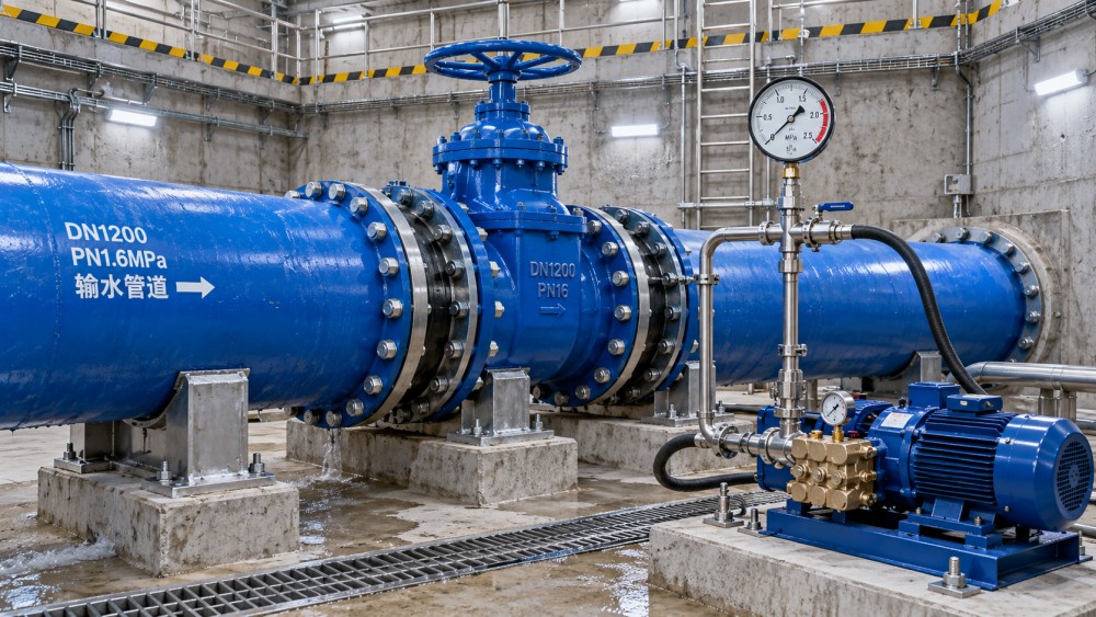
Flanged connections deserve particular attention in plant rooms, valve chambers, pump stations, and equipment interfaces. Their advantage is accessibility, but their sealing reliability is sensitive to flange-face condition, bolt grade, washer use, gasket selection, tightening sequence, and torque control. Uneven bolt loading can distort a gasket or leave a leak path that appears only after thermal changes, vibration, or repeated pressure cycling. Where dissimilar materials meet, the corrosion and insulation strategy also needs review.
For welded steel pipe, the quality focus shifts toward fit-up, qualified welding procedures, welder qualification, weld inspection, repair control, and restoration of field-applied lining and external coating. A sound weld bead alone is not the entire acceptance story. Damage to a protective coating around a field joint may create a future corrosion location even when the hydrostatic test passes cleanly.
Material Certificates Matter, but So Does Traceability in the Field
Quality records should allow a reviewer to connect delivered materials with approved submittals and the installed route. For pressure pipe, this normally includes manufacturer identification, dimensions, material designation where applicable, pressure class or design information, coating and lining details, and relevant factory test documentation. Fittings, valves, couplings, gaskets, bolts, and restraints should be traceable to the approved product data as well.
This does not mean every project needs an impractical level of serial-number control. The required traceability should match the project risk and contract requirements. Yet mixed deliveries are a genuine concern. A site may receive pipes with similar appearance but different classes, coating systems, or intended services. Once products are stacked, cut, or moved along a long right-of-way, identification can disappear quickly. Inspection teams should verify markings at receipt and maintain a practical material-release process before installation.
Lining and coating inspection is particularly important for high pressure water transmission pipes because damage may not cause immediate leakage. Cement mortar lining, epoxy systems, metallic coatings, polyurethane, polyethylene sleeving, and other protection methods have different inspection needs. The key question is not which system sounds most durable in a brochure; it is whether it is suitable for the conveyed water, soil environment, handling method, field-joint treatment, and anticipated maintenance conditions.
Hydrostatic Testing Is a Controlled Safety Operation
Field hydrostatic testing is one of the most visible acceptance activities, but it should never be approached as a quick pressure check. The test section must be isolated with components capable of resisting the test load. Temporary end closures, test caps, blind flanges, thrust restraint, gauges, hoses, pumps, and connections all need deliberate review. Pressurised temporary works can be more hazardous than the permanent pipeline because they may not have the same engineered restraint or protection.
The exact test pressure, stabilisation period, test duration, permitted makeup water, and acceptance method must come from the project specification and applicable standard. These details vary by pipe material and contract requirements. Teams should not copy a test pressure from a previous project or assume that one material’s procedure applies to another. The governing documents should also state whether testing is conducted by pipeline segment, after jointing, before final backfill, or at another defined installation stage.
Air removal is critical. A pipeline should be filled slowly from a low point while air is released from high points through properly planned vents. Testing a line containing significant trapped air introduces unnecessary stored energy and can produce misleading pressure readings. It can also make a failure more violent. Safety exclusion zones, communications between pump operator and inspectors, calibrated gauges, and a controlled pressurisation rate are basic safeguards—not administrative extras.
What a useful test record should show
A defensible test record identifies the exact section tested, pipe material and diameter, relevant elevations, test medium, target pressure, gauge identification and calibration status, start and finish times, observed pressure behaviour, water added if the specified method requires it, visible leaks, repairs, and witness signatures where required. Photographs can help, especially at temporary restraints, gauge setups, exposed joints, and repaired locations, but they should support rather than replace the written record.
A pressure drop does not automatically identify the cause. Temperature change, trapped air, gauge error, leakage from test equipment, movement at a temporary closure, and actual leakage can all affect the reading. The response should be investigation, not repeated pressurisation until the gauge seems stable. Repeated testing without correcting the cause can damage joints, fatigue temporary equipment, and expose workers to avoidable risk.
Common Failures Begin Before the Test
Many field defects can be prevented by inspecting work before a trench is closed. Particular attention should be given to bedding support, pipe alignment, joint insertion marks, gasket installation, coating damage, restraint placement, valve support, and the transition between pipe materials. Backfilling too early can make a minor defect difficult and expensive to locate. Conversely, leaving a pipeline insufficiently supported during testing can create a problem that would not exist after proper backfill. The sequence needs to follow the approved method statement.
Another recurring weakness is treating fittings as accessories. In reality, a reducer or bend can be the point where thrust, restraint, coating repair, bolt loading, and connection tolerance come together. Inspection plans should allocate adequate hold points to these locations rather than concentrating only on straight pipe installation.
For complex infrastructure packages, the same practical discipline used in machining and heavy industrial equipment applies here: verify the interface, not only the individual component. A pipe may conform to its manufacturing standard, a valve may have acceptable documentation, and a coupling may be approved, yet the assembled interface can still be unsuitable because of pressure mismatch, dimensional incompatibility, missing restraint, or an unaddressed corrosion condition. This is the kind of cross-check that structured piping and equipment knowledge platforms such as IMPE help project teams organise before installation begins.
A Better Acceptance Mindset for Transmission Pipelines
For quality-control and safety teams, acceptance should be based on evidence that the installed system matches the approved design intent. That means confirming pressure duty, material suitability, joint arrangement, restraint detail, installation records, factory documentation, coating and lining condition, and controlled hydrostatic testing. No single certificate or test result can substitute for that chain of evidence.
The practical priority is simple: resolve uncertainty before the line is buried, energised, or placed under routine pressure. A questionable gasket, unclear pressure class, incomplete restraint detail, or ambiguous test procedure is much cheaper to address during construction than after a transmission main enters service. In high-pressure water work, disciplined inspection is not about creating more forms. It is about preventing a manageable installation issue from becoming a water-loss event, an asset failure, or a safety incident.
Related News
- How to Assess a Rigid Coupling Supplier for Bore Accuracy and Traceable QualityOct 08, 2026Tribology & Kinematics Expert
- Titanium Alloys Compared: Balancing Strength, Corrosion Resistance, and MachinabilityOct 08, 2026CNC Kinematics Architect
- Where Ductile Iron Dismantling Joints Reduce Alignment Risk in Water PipelinesOct 08, 2026Pipeline Metallurgy Scientist
- Selecting a Precision Bearing Sleeve: Fits, Runout, and Material ChoicesOct 08, 2026Tribology & Kinematics Expert
- Face Milling Cutters: How Insert Geometry Affects Finish on Steel and AluminumOct 08, 2026CNC Kinematics Architect
- Single-Acting Cylinders for Clamping: Stroke, Force, and Return Spring ConsiderationsOct 07, 2026Fluid Power Control Strategist