
Ductile Iron Valves for Water Networks: Pressure Class and Coating Checks
The most costly inspection error with ductile iron valves is treating the pressure marking and the coating specification as separate checks. They are not. A valve body may carry an acceptable PN rating yet fail prematurely because its bolts, flange drilling, seat arrangement, lining, or external coating are unsuitable for the actual network. Conversely, a heavy epoxy coating does not compensate for a valve that has been selected against nominal pressure rather than the system’s full pressure envelope.
For water networks, acceptance should establish one clear point: the delivered valve is suitable for the specified service pressure, transient conditions, connection standard, water quality, burial or exposure environment, and operating duty. “Ductile iron” describes the body material, not the complete performance level of the valve assembly.
Pressure class must be read as a system requirement, not a nameplate number
Pressure designation is often the first item checked on a valve body, but it is also one of the most frequently misunderstood. In European waterworks specifications, valves are commonly designated PN 10, PN 16, or PN 25. PN is a nominal pressure designation expressed in bar and used for compatibility within a defined temperature range. It is not a guarantee that every component will tolerate every pressure event at that value under all service conditions.
In North American specifications, pressure may instead be stated in psi, with valve requirements linked to standards such as AWWA C509 or AWWA C515 for resilient-seated gate valves, and AWWA C504 for rubber-seated butterfly valves. ANSI/ASME pressure classes, such as Class 150, also appear in industrial piping documents. These designations cannot be converted casually into PN ratings. Flange dimensions, bolt patterns, allowable temperatures, test requirements, and intended service categories can differ even where nominal pressure figures appear similar.
A pressure-class review therefore starts with the project specification and the piping design basis rather than the valve catalogue. The acceptance record should identify:
- normal operating pressure at the valve location;
- maximum static pressure, including elevation effects and pump shutoff conditions;
- surge or water-hammer pressure expected during pump trips, rapid closing, air release events, and emergency isolation;
- vacuum or sub-atmospheric conditions where pipeline draining, pump suction, or transient separation may occur;
- the compatible pressure rating of mating pipes, fittings, flanges, dismantling joints, couplings, and bolts.
A valve installed at the lower end of a pressure zone can experience a materially higher static pressure than one located near the source or at a higher elevation. Selecting all valves to a single network-wide nominal rating without checking hydraulic zones can create hidden weak points. The same concern applies to valves adjacent to pump stations, pressure-reducing stations, reservoirs, and long rising mains, where transient loading may govern the design.
Valve type also matters. A gate valve used for isolation is normally required to operate fully open or fully closed, while a butterfly valve may be selected for isolation, regulation, or both depending on its design and specified duty. Using an isolation valve for frequent throttling can damage seats, coatings, discs, and downstream piping even when the pressure class is technically correct.
Do not accept mixed standards without checking the interface
For flanged ductile iron valves, the body rating alone does not establish interchangeability. The flange drilling, facing, bolt circle, flange thickness, gasket arrangement, and bolt grade must match the connected system. EN 1092-2 is commonly used for cast iron flanges in European-design systems, while ASME B16.1 and AWWA flange conventions may be encountered in other markets. Similar-looking flanges may not share the same dimensions or pressure-temperature basis.
Face-to-face or end-to-end dimensions require the same attention. EN 558 provides face-to-face and centre-to-face dimensions for industrial valves, but the required series must be identified in the contract documents. A valve that fits the flange drill pattern but has the wrong laying length can force field modifications, induce pipe stress, or make replacement impossible without removing adjacent pipework.
For water-supply valves, the EN 1074 series is a key reference family. EN 1074-1 establishes common requirements, while the relevant part depends on function: EN 1074-2 covers isolating valves, EN 1074-3 check valves, EN 1074-4 air valves, and EN 1074-5 control valves. These standards should be read alongside the project’s pressure, material, test, and drinking-water requirements; citing the standard name alone does not define every product detail.
Where the project follows AWWA practice, the valve standard must match the valve type and size range. A declaration of compliance with “AWWA standards” is too broad to support acceptance. The purchase order should name the applicable document, revision required by the contract, dimensional requirements, pressure rating, coating system, and test obligations.
Pressure testing should verify both shell integrity and seat performance
Hydrostatic testing is not merely a manufacturing formality. It provides evidence that the pressure boundary and closure system performed under defined test conditions before dispatch. EN 12266-1 and ISO 5208 are widely referenced for pressure testing of industrial valves, while AWWA product standards set requirements for the valve categories they cover. The applicable test method must be tied to the governing product standard rather than selected by convenience.
Inspection records should distinguish at least two different outcomes:
- Shell strength and tightness: confirmation that the body, bonnet, end connections, and pressure-retaining joints do not leak or show distress under the required hydrostatic test condition.
- Seat tightness: confirmation that the closure element and seat achieve the specified leakage performance in the required flow direction and pressure condition.
A passed shell test does not prove acceptable shut-off performance. Likewise, a satisfactory seat test does not prove the body has sufficient integrity. The test certificate should identify the valve tag or serial number, nominal diameter, pressure designation, test medium, relevant test pressure, hold period where specified, result, date, and traceability to the manufacturing batch.
For resilient-seated gate valves, inspection should also confirm the wedge geometry, rubber encapsulation condition, stem arrangement, and full open/closed travel. For butterfly valves, critical checks include disc alignment, shaft retention, seat condition, actuator travel stops, and the relationship between the indicated position and the actual disc position. A valve that closes against the wrong mechanical stop can appear operable during a brief functional check while failing to achieve reliable isolation in service.
Field hydrostatic testing after installation remains necessary, but it should not be used to replace factory acceptance testing. Site tests evaluate the installed system, including joints and workmanship. Factory tests establish baseline evidence for the valve itself. When a leak is discovered only after burial or commissioning, separating these two responsibilities becomes far more difficult.
Coating checks need to address preparation, continuity, and service exposure
External coating is often the main corrosion barrier for buried ductile iron valves. Internal coating or lining protects the wetted surface and can affect water quality, operating torque, and long-term corrosion behaviour. A coating description such as “epoxy coated” is incomplete unless it identifies the system, surface preparation, dry film thickness, curing method, repair procedure, and applicable performance standard.
For waterworks valves, fusion-bonded epoxy and liquid epoxy systems are frequently specified. AWWA C550 is widely used for protective epoxy coatings on valves and hydrants. In EN-based projects, coating requirements may be stated through the valve specification, purchaser requirements, or related corrosion-protection standards. The governing requirement should be explicitly listed rather than inferred from the country of manufacture.
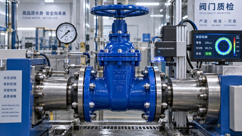
Coating acceptance should not stop at a visual review of smooth, glossy surfaces. The highest-risk locations are often the places least visible after assembly: flange edges, bolt holes, bonnet joints, stem areas, actuator mounting faces, underside cavities, and repaired casting imperfections. These locations are vulnerable to thin film, mechanical damage, incomplete coverage, or early coating breakdown.
A practical coating-control record should address the following points:
- Surface preparation: the specified cleanliness and profile must be achieved before coating. Residual moulding sand, rust, oil, casting scale, or sharp edges can undermine adhesion.
- Film thickness: measurements should be taken at representative accessible positions, with attention to edges and complex geometry. An average value cannot conceal local thin areas where corrosion will initiate.
- Holiday detection: where required by the coating system and specification, electrical continuity testing can identify pinholes and discontinuities. Test voltage must be appropriate for the cured coating thickness to avoid damaging the film.
- Curing and handling: an epoxy film can look intact but remain insufficiently cured or be damaged during packing, lifting, and transport. Handling points deserve inspection at delivery.
- Repair control: repaired areas should use an approved compatible material and follow the specified preparation and cure process. Unrecorded touch-up is not equivalent to a verified repair.
The external exposure category must be defined realistically. Standard epoxy may be suitable for many buried water applications, but aggressive soils, tidal or splash exposure, permanent immersion, stray-current environments, and chemically contaminated ground may require additional protection or a different system. The valve’s coating cannot be assessed independently from the protection strategy for the connected pipework, fittings, bolts, and flange joints.
Internal surfaces require separate scrutiny. Water-contact coatings, linings, elastomer seats, lubricants, and sealing compounds should be suitable for the conveyed water and the jurisdiction’s potable-water requirements where applicable. NSF/ANSI/CAN 61, WRAS approval, ACS attestation, and other national schemes are not interchangeable certificates; acceptance depends on the applicable regulatory route and the actual materials in contact with drinking water.
Body integrity includes material traceability and casting quality
Ductile iron delivers useful strength and toughness, but the term does not eliminate the need for material control. The purchase specification should identify the required material grade or governing standard, such as EN 1563 where applicable, and define the documentation expected for critical projects. Material certificates should be traceable to the valve or production lot in a manner consistent with the project’s quality plan.
Visual examination should look for evidence of casting defects, grinding repairs, cracks, distorted flanges, damaged threads, incomplete machining, and rough internal areas likely to affect flow or coating adhesion. A smooth paint layer must not be accepted as proof that the substrate is sound. Where non-destructive testing, radiography, magnetic particle inspection, or ultrasonic examination is required, the extent and acceptance criteria need to be stated in the contract. Such tests are not universally required for every municipal valve and should not be imposed without a defined risk basis.
Fasteners, stems, shafts, bearings, seals, and actuators also belong in the integrity review. A ductile iron body with an unsuitable stem material or unprotected external fasteners can create a failure mode unrelated to the casting itself. For buried valves, confirm the compatibility of extension spindles, surface boxes, operating nuts, and access arrangements. Improper alignment can introduce side loading on the stem and leave the valve difficult to operate after backfilling.
Documentation should make nonconformities visible before installation
The strongest acceptance process links the physical valve to a controlled set of documents. At minimum, the package should reconcile the purchase order, approved data sheet, general arrangement drawing, valve marking, material declaration where required, hydrostatic test record, coating inspection record, and any potable-water conformity documentation required for the destination market.
Markings should be legible and durable enough to remain useful through storage and installation. They commonly include manufacturer identification, nominal size, pressure designation, body material indication or traceability mark, and production or serial identification as required by the governing standard. Missing or inconsistent markings are not a minor administrative defect when they prevent a valve from being linked to its test certificate.
Release should be withheld when pressure class, flange standard, coating system, or test documentation is unclear. These are not matters that can safely be resolved by assuming equivalence after delivery. In water networks, valves are expected to remain accessible only through chambers, valve boxes, or planned shutdowns. The most effective control point is therefore before installation, when a mismatch can still be isolated without excavation, service interruption, or uncertainty over liability.
Related News
- How to Assess a Rigid Coupling Supplier for Bore Accuracy and Traceable QualityOct 08, 2026Tribology & Kinematics Expert
- Titanium Alloys Compared: Balancing Strength, Corrosion Resistance, and MachinabilityOct 08, 2026CNC Kinematics Architect
- Where Ductile Iron Dismantling Joints Reduce Alignment Risk in Water PipelinesOct 08, 2026Pipeline Metallurgy Scientist
- Selecting a Precision Bearing Sleeve: Fits, Runout, and Material ChoicesOct 08, 2026Tribology & Kinematics Expert
- Face Milling Cutters: How Insert Geometry Affects Finish on Steel and AluminumOct 08, 2026CNC Kinematics Architect
- Single-Acting Cylinders for Clamping: Stroke, Force, and Return Spring ConsiderationsOct 07, 2026Fluid Power Control Strategist