
How to Verify Valve Body Casting Quality Before Project Acceptance
A valve body can look acceptable on a pallet and still create serious trouble once it is installed in a buried water network, pumping station, treatment plant, or industrial pipeline. A small shrinkage cavity near a flange, an undocumented material substitution, or an uneven coating system may not be obvious during a fast receiving inspection. Yet each can lead to leakage, corrosion, pressure-test failure, delayed commissioning, and an uncomfortable dispute over who carries the cost.
For municipal EPC teams, utilities, distributors, and OEM buyers, shipment acceptance is therefore more than a warehouse activity. It is the final opportunity to confirm that the supplied valve bodies match the approved drawings, technical specification, material requirements, and project documentation before ownership and installation risk shift to the buyer.
How to verify valve body casting quality before accepting a water project shipment?
The most reliable approach is to compare four things rather than relying on appearance alone: the purchase specification, the physical casting, the inspection evidence, and the traceability link between them. Material certificates, visual inspection, non-destructive examination, dimensional records, hydrostatic pressure tests, and coating reports should all tell the same story. If they do not, the shipment should be placed on hold until the discrepancy is understood and formally resolved.
For water-service valves, this matters especially because the body is the pressure-containing structure. Seals, actuators, and trim can often be repaired or replaced; a defective body casting usually cannot be corrected economically after installation.
Begin with the approved acceptance basis—not the supplier’s standard paperwork
Before opening crates or selecting samples, the receiving team should assemble the documents that define what was actually ordered. These normally include the purchase order, approved valve datasheet, drawings, applicable material standard, pressure class, inspection and test plan (ITP), coating specification, and any project-specific acceptance clauses.
Water projects frequently use ductile iron, cast iron, cast steel, stainless steel, or duplex stainless steel valve bodies depending on pressure, media, installation environment, and corrosion requirements. A certificate stating that a casting is “iron” or “steel” is not sufficient. The grade, heat number, mechanical properties, chemical composition, casting standard, and pressure rating must align with the contractual specification.
A practical receiving review asks a simple question: Can every delivered valve body be connected to the exact requirement that governs it? If the project calls for a particular ductile iron grade, epoxy thickness, flange drilling pattern, and hydrostatic test pressure, those requirements should be visible in the documents and verifiable on the product.
Documents that should be available before release
- Material test certificates for the body casting, linked to heat or melt numbers.
- Certificate of conformity identifying valve type, size, pressure rating, and quantity.
- Dimensional inspection reports for critical interfaces.
- Hydrostatic shell test and, where applicable, seat leakage test records.
- Non-destructive testing reports when required by the specification or risk category.
- Coating inspection reports, including surface preparation and dry film thickness.
- Traceability register connecting serial numbers, body markings, test records, and shipment packing list.
- Records of approved repair welding, deviations, or concessions, if any.
Do not treat a stack of certificates as proof by itself. Check whether the part numbers, dimensions, quantities, dates, heat numbers, and inspector identification correspond to the shipment in front of you. Documentation that cannot be tied to individual units or defined batches has limited value during a later claim.
Compare what your eyes can see with what the casting process can hide
Visual inspection remains the fastest way to identify handling damage, poor finishing, and obvious foundry defects. It is also where project teams can quickly discover whether the shipment was protected adequately during transport. However, visual inspection cannot confirm internal soundness. It should be treated as the first filter, not the final verdict.
Inspect body surfaces under adequate lighting. Look around flange transitions, bonnet connections, branch intersections, seat areas, lifting points, and changes in wall section. These locations are more vulnerable to stress concentration, incomplete filling, shrinkage-related defects, or coating damage.
Common warning signs include rough or irregular surfaces, sand inclusions, cold shuts, visible cracks, porosity, excessive grinding, patched areas, distorted flanges, damaged threads, and sharp unblended casting transitions. A casting does not have to be cosmetically perfect to be acceptable, but surface condition must remain within the governing standard and must not compromise wall thickness, pressure integrity, sealing surfaces, or corrosion protection.
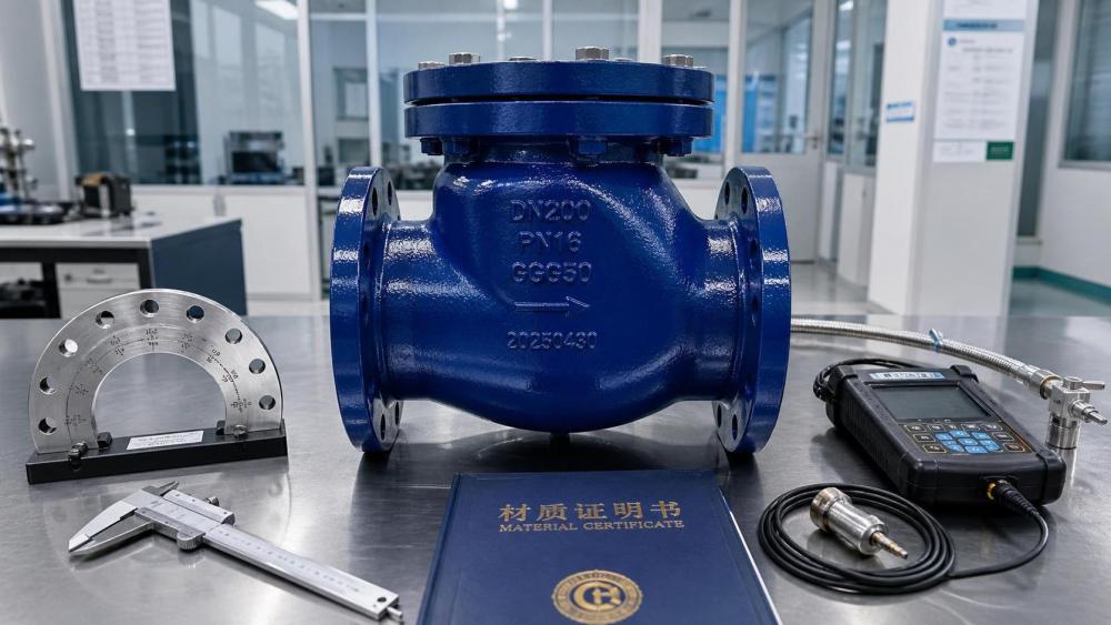
One issue deserves particular caution: extensive grinding can make a casting look cleaner while concealing a deeper discontinuity. Ask whether the supplier’s finishing or repair procedure permits the observed work. If suspected repair welding is found but is absent from the quality dossier, treat it as a nonconformance until the manufacturer provides an approved repair record and any required follow-up examination.
Use the right test for the risk: visual inspection versus NDT versus pressure testing
These methods are often discussed together, but they answer different questions. A buyer who understands the distinction can avoid both under-inspection and unnecessary testing.
For ductile iron and carbon steel valve bodies, magnetic particle testing can be useful for locating surface-breaking cracks in critical zones. Liquid penetrant testing is commonly used on nonmagnetic materials or finely machined surfaces. Ultrasonic testing may help assess wall thickness or internal discontinuities, while radiography can provide a more detailed view of selected internal areas. The right method depends on material, wall section, geometry, code requirements, and the consequence of failure.
It is a mistake to request “100% NDT” without defining the method, acceptance criteria, areas to be examined, and reporting format. More testing is not automatically better if the scope is vague. A well-written inspection plan identifies the critical zones and the applicable acceptance standard.
Pressure test records must match the delivered valve configuration
A hydrostatic test record is one of the most important documents in a water valve shipment, but it needs careful reading. Confirm that the recorded valve size, pressure rating, serial number or traceable batch number, test medium, test pressure, hold time, and acceptance result match the applicable project requirement.
Shell testing verifies that the pressure boundary did not leak under the specified test condition. Where the valve is supplied assembled, seat testing may also verify closure performance. These are related but different results. A passed seat test does not replace shell integrity evidence, and a passed shell test does not prove that the seat will meet the required leakage class.
If the project requires third-party witnessing, factory acceptance testing, or pre-shipment inspection, verify that the relevant signatures and dates are present. A generic pressure-test certificate issued after shipment, without unit-level traceability, should not be treated as equivalent to witnessed testing.
Measure the dimensions that can stop installation
In project reality, a valve body can be structurally sound and still delay a pipeline installation because its interfaces do not fit. Receiving inspection should prioritize dimensions that affect field assembly, maintenance access, and compatibility with connected equipment.
For flanged water valves, confirm nominal diameter, flange outside diameter, bolt circle, hole count, hole diameter, flange face condition, flange thickness, face-to-face or end-to-end dimension, and alignment of the bore. Check the flange drilling standard carefully; visually similar flange patterns may not be interchangeable. For valves with threaded, grooved, wafer, or mechanical-joint ends, use the corresponding project dimensions and connection standard.
Pay attention to flange flatness and perpendicularity where practical. A warped flange can create uneven gasket compression, while a misaligned bore can affect flow or prevent correct connection to pipework. For larger-diameter valves, an inspection team may use calibrated tapes, calipers, flange gauges, depth gauges, and templates. Critical dimensions should be verified using equipment appropriate to the stated tolerances.
Coating is not merely cosmetic in a water infrastructure project
Many valve bodies for water distribution and wastewater duty rely on external and internal coating systems for long-term corrosion resistance. Acceptance should therefore review both visible condition and coating evidence. Check for scratches, chips, pinholes, runs, bare edges, weak adhesion, contamination, and damage around flange faces, bolt holes, and lifting locations.
Coating reports should identify the coating type, surface preparation standard, application process, dry film thickness measurements, curing information where applicable, and repair procedure. If the valve will be buried, installed in a humid chamber, exposed to aggressive soil, or used in wastewater service, the coating requirement may be particularly consequential.
Thickness readings alone are not enough. Excessively thick coating can crack or interfere with fit-up; inadequate thickness can reduce protection. The correct benchmark is the project specification and the coating manufacturer’s approved system, not a general assumption that more coating is always better.
Traceability is the bridge between a valve body and its evidence
Every accepted valve body should carry durable identification that can be linked to the quality file. Depending on the project, this may include the manufacturer’s mark, casting heat number, batch number, serial number, size, pressure class, material designation, and production date or code.
Check markings against the packing list and certificates. If labels are only on cartons, they can be lost during staging or installation. Permanent body markings are more reliable, provided they do not damage the pressure boundary or obscure essential information.
Traceability becomes vital when a field issue emerges months later. Without it, the project team may be unable to isolate affected units, confirm material origin, or distinguish a single damaged delivery from a wider production problem.
Set acceptance decisions before the inspection starts
Receiving teams work more consistently when they define what “accept,” “hold,” and “reject” mean in advance. This avoids a common problem: a shipment is informally accepted because installation pressure is high, then disagreements surface after the goods are already distributed across the site.
- Accept: Documentation is complete, physical inspection is satisfactory, measurements meet tolerance, and all required tests are traceable to the delivered units.
- Accept with documented minor punch items: Only non-safety-critical, repairable issues exist, such as limited transport coating damage, with a mutually agreed repair and verification process.
- Hold for clarification: There are missing certificates, inconsistent heat numbers, unclear NDT scope, incomplete test data, or suspicious surface conditions requiring additional examination.
- Reject or segregate: Pressure failure, unapproved material substitution, cracks, major dimensional mismatch, undocumented weld repair, or defects beyond the applicable acceptance criteria are identified.
Sampling plans should also reflect risk. A small batch of large, high-pressure, difficult-to-replace valves deserves closer scrutiny than a large lot of low-risk standard components. If the supplier has a new production source, the delivery is for a critical transmission main, or the project has already experienced quality issues, expand the inspection scope rather than relying on a minimal sample.
A disciplined acceptance process protects the schedule as well as the pipeline
Knowing how to verify valve body casting quality before accepting a water project shipment is ultimately about preventing uncertainty from entering the construction phase. The strongest process does not depend on a single certificate, one visual check, or trust in a familiar supplier. It compares material identity, casting integrity, dimensions, pressure-test performance, coating condition, and traceable records against the approved project basis.
When a discrepancy appears, document it with photographs, unit identification, measured values, and the exact specification reference. Segregate affected goods, issue a formal nonconformance report, and agree on disposition before installation. That discipline may feel slow at the receiving dock, but it is far less disruptive than excavating a failed valve, interrupting water service, or explaining a preventable defect after project handover.
Related News
- How to Assess a Rigid Coupling Supplier for Bore Accuracy and Traceable QualityOct 08, 2026Tribology & Kinematics Expert
- Titanium Alloys Compared: Balancing Strength, Corrosion Resistance, and MachinabilityOct 08, 2026CNC Kinematics Architect
- Where Ductile Iron Dismantling Joints Reduce Alignment Risk in Water PipelinesOct 08, 2026Pipeline Metallurgy Scientist
- Selecting a Precision Bearing Sleeve: Fits, Runout, and Material ChoicesOct 08, 2026Tribology & Kinematics Expert
- Face Milling Cutters: How Insert Geometry Affects Finish on Steel and AluminumOct 08, 2026CNC Kinematics Architect
- Single-Acting Cylinders for Clamping: Stroke, Force, and Return Spring ConsiderationsOct 07, 2026Fluid Power Control Strategist