
Why Heat-Treated Forged Rollers Develop Surface Cracks and Fail Prematurely
When heat-treated forged rollers crack at the surface, maintenance teams should treat the damage as a process-and-service failure, not simply a cosmetic defect.
Cracks can rapidly grow under cyclic loading, contaminate adjacent components, damage bearings, and trigger unplanned shutdowns in mills, conveyors, presses, and heavy-duty machinery.
For after-sales maintenance personnel, the immediate objective is to identify whether the crack started during manufacturing, finishing, installation, lubrication failure, or actual operating overload.
What Surface Cracks Usually Mean in Forged Rollers
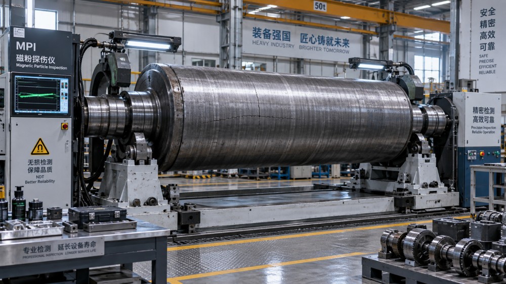
Surface cracks in heat treated forged rollers commonly indicate excessive tensile stress, insufficient toughness, local overheating, grinding damage, hydrogen effects, or pre-existing metallurgical discontinuities.
The crack pattern matters. Straight axial cracks, circumferential cracks, fine grinding checks, and branching fatigue cracks each point toward different root causes and inspection priorities.
A roller may continue operating briefly after cracking begins, but cyclic contact pressure can force cracks deeper into the forged section and weaken load-bearing capacity.
Maintenance personnel should not assume that hardness alone proves roller quality. A high hardness result may coexist with poor tempering, brittle microstructures, or harmful residual stress.
The most useful first question is whether the crack originated at the surface and propagated inward, or began below the surface from an inclusion or forging defect.
Why Heat Treatment Creates a High-Risk Stage
Heat treatment gives forged rollers the hardness, wear resistance, strength, and toughness needed for service, but poor temperature control can create damaging internal stress.
During heating, soaking, quenching, and tempering, the roller section expands and contracts unevenly. Large diameters and changing cross-sections make this behavior more difficult to control.
If the surface cools much faster than the core, transformation stresses can develop. These stresses may remain after processing and become crack initiation sites during operation.
Quenching too aggressively can produce excessive martensite at the surface. Martensite provides hardness, but untempered or poorly tempered martensite is brittle and crack-sensitive.
Quenching too slowly can also be problematic. It may produce uneven hardness, mixed microstructures, and localized weak zones that deform under repeated contact loading.
Forged rollers with keyways, shoulders, grooves, oil holes, weld repairs, or abrupt diameter changes require special attention because geometric transitions concentrate heat-treatment stress.
Uniform furnace loading, monitored soak time, correct quench media, controlled agitation, and prompt tempering are therefore essential for consistent roller performance.
Improper Quenching and Tempering Are Frequent Root Causes
A common failure mechanism is severe quench cracking. This often occurs when the roller enters quench media at an unsuitable temperature or experiences excessive cooling intensity.
Water quenching can create steep temperature gradients in many alloy steel rollers. Oil, polymer, air, or staged quenching may be more appropriate depending on steel grade.
Delayed tempering is another serious risk. A newly quenched roller can retain high residual stress and brittle microstructure until tempering reduces stress and restores toughness.
Insufficient tempering temperature may leave the surface too hard and brittle. Excessive tempering temperature may lower hardness below the specified wear-resistance requirement.
Multiple tempering cycles may be necessary for some forged roller materials, especially where dimensional stability, fatigue resistance, and retained stress reduction are critical.
Maintenance teams reviewing failed heat treated forged rollers should request furnace charts, quench records, tempering records, hardness maps, and material heat numbers.
These documents help distinguish a process deviation from a field-service problem. Without traceability, replacement decisions can become based on assumptions rather than evidence.
Material Chemistry and Forging Quality Can Start the Problem Earlier
Not every crack is caused by the final heat-treatment cycle. The failure may originate from unsuitable chemistry, poor steel cleanliness, segregation, inclusions, or insufficient forging reduction.
Forging should refine grain structure and close internal discontinuities. However, inadequate deformation can leave coarse grains or segregated areas that respond unevenly during heat treatment.
Non-metallic inclusions can become local stress raisers. Under rolling contact fatigue, cracks may start at these sites and later become visible at the roller surface.
Improper sulfur, phosphorus, carbon, chromium, molybdenum, or nickel levels can alter hardenability and toughness. Material must match both the heat-treatment process and service load.
A material certificate confirms nominal composition, but it does not alone demonstrate sound forging quality. Ultrasonic testing and macroetch evaluation may reveal internal quality issues.
For critical rollers, maintenance teams should verify whether the supplier performed ultrasonic examination before machining and whether acceptance limits were clearly defined in the purchase specification.
When multiple rollers from the same batch crack similarly, material and heat-treatment batch records should be investigated before blaming individual operating conditions.
Grinding Damage Can Turn a Sound Roller into a Cracked Roller
Grinding is often the final operation before delivery, and it can create surface damage even when forging and heat treatment were otherwise acceptable.
Excessive grinding pressure, dull abrasive wheels, incorrect wheel specification, inadequate coolant flow, or poor dressing can overheat the roller surface within seconds.
Grinding burns alter local microstructure and introduce tensile residual stress. Fine crack networks, sometimes called grinding checks, may be difficult to see without inspection methods.
These cracks are especially dangerous because they are already located at the contact surface, where rolling pressure, friction, and thermal cycling are highest.
Visual inspection alone may miss shallow grinding cracks. Magnetic particle inspection is useful for ferromagnetic rollers, while dye penetrant testing can reveal open surface discontinuities.
Hardness measurements should be taken at several positions, but technicians should avoid interpreting isolated readings without considering the expected hardened layer depth and component geometry.
When grinding damage is suspected, request records for wheel type, feed rate, coolant concentration, spark-out practice, surface roughness, and post-grinding inspection results.
Residual Stress Becomes Dangerous During Real Service
Residual stress is not always visible, but it strongly affects premature roller failure. Tensile stress at the surface encourages crack opening under normal operating loads.
Compressive surface stress generally improves fatigue resistance because it resists crack initiation. Some finishing processes can preserve or introduce beneficial compressive stress.
Shot peening, controlled rolling, and carefully selected finishing processes may improve fatigue performance, but they cannot correct deep metallurgical defects or improper core heat treatment.
Residual stress can also change after machining, grinding, thermal exposure, or repeated overload. A roller that passed initial inspection may later become vulnerable.
Maintenance teams should compare crack location with contact zones, bearing seats, transition radii, drive connections, and areas exposed to concentrated thermal or mechanical loading.
Cracks near shoulders or keyways often suggest stress concentration. Cracks distributed across the rolling surface more often suggest grinding damage, overload, or contact fatigue.
Overload, Misalignment, and Poor Contact Conditions Accelerate Failure
Even correctly manufactured heat treated forged rollers can crack prematurely when operating loads exceed design limits or contact conditions become unstable.
Misalignment causes load concentration along one edge of the roller. This can produce localized overheating, uneven wear, high contact stress, and fatigue crack initiation.
Incorrect bearing installation may allow shaft deflection or roller tilt. The resulting edge loading can be more destructive than a moderate increase in overall load.
Contaminated lubrication increases friction and surface temperature. Metal particles, water ingress, incorrect viscosity, or lubricant starvation can quickly damage hardened rolling surfaces.
Thermal shock should also be considered. Rollers exposed to rapid heating and cooling may develop surface stress, particularly in process lines handling hot materials.
Repeated start-stop cycles, impact loading, vibration, and torque reversals all increase fatigue demand. Maintenance records should capture these conditions during failure analysis.
A replacement roller will not solve the underlying problem if the machine remains misaligned, overloaded, poorly lubricated, or exposed to the same abnormal thermal cycle.
How to Inspect Cracked Forged Rollers Systematically
Begin by making the equipment safe, isolating energy sources, and documenting the roller location, orientation, running hours, load conditions, lubrication condition, and failure symptoms.
Photograph the crack before cleaning or grinding. Record its direction, length, width, location, and relationship to welds, shoulders, grooves, bearing positions, and contact tracks.
Clean the affected surface carefully. Heavy oxide, oil, paint, or debris can conceal the crack pattern and reduce the reliability of magnetic particle or penetrant testing.
Use magnetic particle testing for surface and near-surface cracks in ferromagnetic steels. Apply testing in more than one magnetization direction where crack orientation is uncertain.
Dye penetrant testing can identify open cracks, especially after surface cleaning. However, it cannot reliably show subsurface discontinuities or determine crack depth.
Ultrasonic testing is valuable for evaluating deeper cracking, internal inclusions, and forging discontinuities. Interpretation should account for roller geometry and material attenuation characteristics.
Measure hardness around damaged and undamaged zones. Significant variation may indicate uneven heat treatment, localized grinding burn, decarburization, or service-related thermal damage.
For major failures, remove a representative sample for metallographic examination. Microstructure, fracture appearance, decarburization depth, and inclusion content often provide decisive evidence.
Crack Pattern Can Help Identify the Likely Cause
Fine, shallow, closely spaced cracks crossing the surface often indicate grinding checks or rapid thermal damage. They may appear as a network under magnetic particle inspection.
Long axial cracks can be associated with quench stress, forging directionality, or longitudinal stress concentration. Their origin should be checked against manufacturing history.
Circumferential cracks may develop from bending stress, excessive radial loading, shrink-fit stress, or thermal cycling. Their position relative to shoulders is especially important.
Branching cracks with polished edges may indicate progressive fatigue. These usually require investigation of load cycles, alignment, lubrication condition, and rolling contact pressure.
Cracks beginning at pits, dents, corrosion marks, or handling damage often show how seemingly minor surface defects can become fatigue initiation points.
Fracture surfaces should not be polished or altered before technical review. Beach marks, initiation zones, and brittle regions can be lost during unplanned repair attempts.
When Repair Is Acceptable and When Replacement Is Necessary
Not every visible mark requires replacement, but a confirmed crack in a critical load-bearing roller should be evaluated conservatively by qualified engineering personnel.
Light surface scoring or non-crack grinding marks may sometimes be removed within dimensional limits. The repaired surface must maintain specified roughness, hardness, and geometry.
Crack removal by grinding is only acceptable when inspection confirms complete removal, remaining wall or diameter is adequate, and the repair does not compromise heat-treated properties.
Welding a cracked hardened roller is rarely a simple repair. Welding introduces heat-affected zones, residual stress, hardness changes, and potential hydrogen cracking risks.
For safety-critical, high-speed, high-load, or fatigue-sensitive applications, replacement is generally more reliable than weld repair, particularly when crack depth is uncertain.
Any repaired roller should undergo appropriate non-destructive testing, dimensional verification, runout measurement, balancing assessment where applicable, and controlled recommissioning.
How Maintenance Teams Can Prevent Repeat Roller Failures
Prevention begins with accurate failure records. Track roller type, supplier batch, material grade, heat-treatment condition, operating hours, crack location, and machine conditions.
Establish inspection intervals based on load severity, production cycles, temperature exposure, and prior failure history. Waiting for visible cracks may be too late.
Monitor vibration, bearing temperature, lubrication cleanliness, roller runout, and alignment. These operating indicators can reveal abnormal conditions before cracking becomes extensive.
During installation, verify bearing fits, shaft alignment, mounting torque, contact geometry, and correct lubrication. Improper assembly can destroy an otherwise sound component.
Specify acceptable roller hardness ranges, hardened depth, surface roughness, dimensional tolerances, ultrasonic testing criteria, and magnetic particle testing requirements in procurement documents.
Require supplier traceability from steel heat through forging, heat treatment, machining, final inspection, and shipment. This makes field failures easier to investigate and contain.
For repeat applications, share field performance data with the supplier. A capable manufacturer can adjust material selection, forging reduction, tempering practice, or finishing methods.
What to Request from a Forged Roller Supplier
Maintenance teams should request more than a basic certificate of conformity. Reliable suppliers should provide material certificates, heat-treatment reports, hardness data, and dimensional inspection records.
For demanding equipment, request non-destructive testing documentation, including ultrasonic testing and magnetic particle inspection methods, acceptance standards, inspection coverage, and technician qualification information.
Discuss the actual operating environment with the supplier. Load peaks, temperature, speed, corrosion exposure, lubrication type, and expected service life affect suitable roller design.
Ask whether the roller was forged from billet, produced with adequate reduction ratio, normalized before final heat treatment, and machined with controlled grinding practices.
Supplier communication should include clear drawings, critical dimensions, contact profiles, tolerances, surface finish requirements, hardness range, and any applicable international or customer standards.
When replacement urgency is high, avoid accepting undocumented substitutes. A lower-cost roller with unknown metallurgy can create larger downtime and warranty costs later.
Final Maintenance Decision
Surface cracks in heat treated forged rollers are early warnings of a broader metallurgical, manufacturing, finishing, installation, or operating condition problem.
The fastest reliable response is to document the crack pattern, perform appropriate non-destructive testing, review machine conditions, and verify the component’s manufacturing traceability.
After-sales maintenance teams should focus on evidence rather than assumptions. Crack location, hardness variation, inspection results, service history, and supplier records usually reveal the most likely cause.
By correcting both the failed roller and the conditions that caused the failure, organizations can reduce repeat damage, protect adjacent equipment, and improve long-term operating reliability.
Related News
- How to Assess a Rigid Coupling Supplier for Bore Accuracy and Traceable QualityOct 08, 2026Tribology & Kinematics Expert
- Titanium Alloys Compared: Balancing Strength, Corrosion Resistance, and MachinabilityOct 08, 2026CNC Kinematics Architect
- Where Ductile Iron Dismantling Joints Reduce Alignment Risk in Water PipelinesOct 08, 2026Pipeline Metallurgy Scientist
- Selecting a Precision Bearing Sleeve: Fits, Runout, and Material ChoicesOct 08, 2026Tribology & Kinematics Expert
- Face Milling Cutters: How Insert Geometry Affects Finish on Steel and AluminumOct 08, 2026CNC Kinematics Architect
- Single-Acting Cylinders for Clamping: Stroke, Force, and Return Spring ConsiderationsOct 07, 2026Fluid Power Control Strategist