
Why Forged Steel Components Withstand Impact Loads in Mining Equipment
Forged steel components withstand mining impacts because forging changes the internal structure of the steel before the final part is machined. Under controlled heat and pressure, the metal is worked into a shape that follows the load path of a shaft, pin, gear blank, linkage, or structural member. This produces directional grain flow, closes much of the internal discontinuity left from earlier processing, and supports a combination of strength, ductility, and fracture resistance that is difficult to obtain from a comparable cast shape.
Impact loading in mining is rarely a single clean event. A shovel pin may receive repeated shock as the bucket engages fragmented rock. A crusher shaft sees torque reversals, vibration, and occasional overloads. Haulage, conveying, drilling, and screening equipment transmit impacts through connected pins, couplings, gears, bearing seats, and hydraulic attachments. Abrasive dust, poor lubrication, misalignment, and temperature changes can add local stress concentrations to an already demanding duty cycle. A component that survives a static load calculation can still fail early if its microstructure, surface condition, or geometry cannot tolerate repeated shock.
Grain Flow Supports the Shape of the Part
Steel is made of many crystals, or grains. During forging, deformation elongates and reorients these grains and the nonmetallic inclusions within the steel. When the forging process is designed around the finished geometry, the grain flow follows the broad contours of the part rather than being cut across randomly.
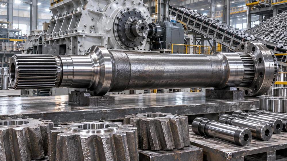
That distinction matters at highly stressed transitions. A forged pin, for example, can be produced with grain flow running along its length and around its head or flange. A forged gear blank can retain flow around the rim and hub before gear teeth are machined. In a shaft with shoulders, fillets, and splined ends, properly directed flow helps the material resist crack initiation where section changes concentrate stress.
Machining a part from bar stock may still provide sound material, particularly for simpler geometry and controlled loads. However, deep machining can sever the favorable flow direction that existed in the starting bar. Casting permits complex shapes but does not create the same wrought grain continuity. Forging is most valuable when the part must absorb high force through a geometry with load-bearing transitions rather than merely occupy a defined envelope.
Grain flow is not a guarantee by itself. If a forging is poorly designed, flow can fold over, become discontinuous at difficult transitions, or fail to reach critical regions. The stated forging method therefore matters less than the relationship between the preform, die sequence, reduction, and final component shape.
Toughness Prevents a Small Crack From Becoming a Sudden Break
Hardness is often used as a quick indicator of wear resistance, but impact service requires a broader view. A very hard steel surface can resist indentation and abrasion while remaining vulnerable to brittle cracking if the underlying material lacks adequate toughness. Mining components often need to deform slightly at a local overload without allowing a crack to run through the full section.
Forged steel commonly offers this balance because the process is followed by heat treatment selected for section size, alloy chemistry, and duty. Quenching and tempering can create a high-strength structure while tempering restores useful toughness. Normalizing, stress relieving, induction hardening, carburizing, or nitriding may also be applied where the component needs a hard working surface with a tougher core. The correct treatment depends on the failure mechanism; there is no universal “harder is better” setting.
A bucket linkage pin illustrates the tradeoff. Its outside diameter must resist abrasive wear and fretting against bushings, while its core must tolerate bending and shear from shock loads. Excessive case depth, an abrupt hardness transition, or a brittle surface layer can create a crack origin instead of extending service life. Conversely, a soft pin can deform, lose fit, and increase impact loading across the entire joint. Material selection, heat-treatment depth, bushing material, lubrication path, and joint clearance need to be evaluated together.
Fatigue Resistance Is Built Around Repeated Stress, Not Peak Load Alone
Many mining failures begin as fatigue cracks rather than immediate overload fractures. The part may carry thousands of cycles below its nominal tensile capacity, yet a local notch, machining mark, corrosion pit, or inclusion raises stress at one small point. Once a crack forms, alternating load gradually extends it until the remaining section can no longer support the applied force.
Forged steel components for mining equipment are well suited to this environment because sound forging practice reduces the chance that internal discontinuities will serve as crack origins. Working the steel can consolidate internal porosity and improve structural uniformity relative to a poorly controlled cast section. It cannot remove every inclusion or correct unsuitable raw material, so melt quality and traceability remain important. A forged part made from inconsistent steel is still an inconsistent part.
Surface condition often determines whether the expected fatigue benefit reaches the field. After forging and heat treatment, shafts, pins, and gear blanks are machined to their final dimensions. Tool chatter, torn metal, burn marks from grinding, sharp keyway corners, and rough transitions can all create local initiation sites. Generous fillet radii, controlled surface finish, and smooth blending at diameter changes are engineering features, not cosmetic refinements.
Threads deserve particular attention. A threaded end exposed to bending or shock can fail at the first loaded thread if the joint is poorly supported. Rolled threads can preserve favorable surface grain flow and introduce compressive residual stress, while cut threads remove material and may leave sharper roots. The preferred choice depends on geometry, finishing sequence, fit requirements, and repair practice, but thread form should never be treated as a minor drawing detail on a heavily loaded component.
What Forging Does Not Solve
Forging improves the material foundation; it does not compensate for a joint that is misaligned, a bearing that has lost lubrication, or a hydraulic cylinder that side-loads its rod. A forged shaft will still fatigue if a coupling imposes excessive angular misalignment. A forged tooth segment or adapter will still crack if weld heat input changes the nearby heat-treated structure without an appropriate repair procedure. A forged pin can seize if contamination enters the lubrication interface and abrasive particles destroy the bushing surface.
Installation can also erase the advantage of a well-made component. Forced assembly through an incorrect interference fit may introduce harmful residual stress or damage a finished surface. Heating a component beyond the intended assembly procedure can alter hardness near a bearing seat or gear hub. Hammering directly on a precision-machined end can create dents that later become fatigue initiation points. Tightening a retaining system without the specified engagement or preload can allow movement, fretting, and impact at interfaces that were designed to remain stable.
Impact marks need interpretation. A bright polished zone around a pin may indicate repeated micro-movement and fretting, not simply normal contact. Circumferential scoring on a shaft may point to bearing damage or contamination. A crack that starts at a fillet often suggests bending stress concentration, whereas a fracture across a reduced section after visible necking suggests gross overload. These patterns guide the investigation toward the actual mechanism rather than assigning the event solely to the material grade.
Critical Process Controls Before Final Machining
Performance depends on the whole manufacturing route. The billet chemistry establishes hardenability, cleanliness, and response to heat treatment. Forging temperature must remain within a range that permits deformation without excessive grain growth or cracking. The die sequence needs sufficient reduction to work the material through the relevant section, especially in large hubs, thick lugs, and stepped shafts.
Cooling after forging also deserves control. Uneven cooling can create residual stress, distortion, or unfavorable transformation products. Large-section parts are particularly sensitive because the surface and core cool at different rates. Heat treatment must then account for actual section thickness rather than a nominal outside dimension alone. A heavy shaft shoulder, gear hub, or pin head may cool differently from the adjoining body, producing property variation if the cycle is not designed for the part geometry.
Forging laps, folds, seams, and surface cracks are serious because they may remain near the finished surface after machining. Removing scale does not prove that such defects are absent. The amount of machining allowance should be compatible with the expected surface condition, and inspection should be planned at the stage where a relevant defect can be detected without being hidden by subsequent operations.
Inspection Should Match the Failure Risk
Dimensional inspection confirms fit, concentricity, runout, and geometry, but it does not establish internal integrity. Visual examination can reveal handling damage, laps, scale-related flaws, and poor blending. Magnetic particle inspection is useful for locating surface and near-surface discontinuities in ferromagnetic steels, particularly around fillets, keyways, threads, and transitions. Ultrasonic examination can assess internal soundness in suitable sections, although geometry, surface preparation, and access affect its effectiveness.
Mechanical test records and hardness results should be read in context. A single hardness reading on an accessible surface does not confirm core toughness, case depth, or uniform response across a large component. Tensile properties provide useful baseline information but do not directly reproduce impact fatigue, abrasive wear, or fretting conditions. Heat-treatment records, material identification, test location, and the relationship between the tested coupon and the final part are often as important as the reported values.
Geometry Can Overrule a Good Material Choice
A forged steel part with a sharp shoulder may perform worse than a lower-strength alternative with a smoother load path. The reason is local stress amplification. Nominal load calculations distribute force across a theoretical cross-section, while the real component concentrates it at grooves, keyways, lubrication holes, thread runouts, weld toes, and sudden changes in thickness.
Lubrication holes in pins and shafts require careful placement. A cross-drilled hole can be necessary for grease distribution, yet it interrupts the load-bearing section. Positioning it near the highest bending region, leaving a rough drilled edge, or allowing the hole to intersect another feature can significantly reduce fatigue life. The preferred arrangement balances serviceability with the actual bending moment diagram and expected direction of load.
Similarly, a forged component should be specified in the final operating orientation where grain direction is relevant. A drawing that permits unrestricted stock orientation or substitution with a generic bar may unintentionally lose the benefit expected from the forging design. The part definition should identify material condition, heat treatment, critical radii, required inspection areas, machining restrictions where relevant, and any controlled orientation needed for the application.
Distinguishing Forging Quality From Service-System Failures
When a forged component fails, the fracture surface and surrounding assembly often reveal whether the root cause lies in manufacturing, design, or operating conditions. A crack aligned with a visible lap or seam raises concern about forging surface quality. An internal origin may require review of ultrasonic results, material cleanliness, and reduction practice. A smooth fatigue zone followed by a rough final overload zone indicates progressive crack growth, but the initiating feature still has to be identified.
By contrast, uniform wear, heat discoloration at a bearing seat, damaged seals, or loosened retainers may point to lubrication failure, contamination, or movement in the assembly. Replacing the component without correcting those conditions repeats the loading environment that caused the damage. Measurements of bore wear, pin clearance, alignment, lubricant condition, and mating-part hardness give more useful evidence than a visual assessment of the broken part alone.
The strongest result comes from treating forged steel as part of an engineered load path. Controlled grain flow and heat treatment provide resistance to impact and fatigue, while machining quality, assembly accuracy, inspection scope, and maintenance preserve that resistance in service. Where those conditions align, forged shafts, gears, pins, and structural members are able to absorb the irregular, repetitive loading that defines heavy mining equipment operation.
Related News
- Using Industrial Air Blow Guns to Clear Chips Without Spreading DebrisOct 15, 2026Fluid Power Control Strategist
- Ductile Iron Pipe Valves: Which AWWA Standards Apply to Water Main Projects?Oct 15, 2026Dr. Elias Vance
- Why Vacuum Suction Cups Lose Grip on MDF in Woodworking MachinesOct 15, 2026CNC Kinematics Architect
- Choosing a Variable Displacement Piston Pump Manufacturer: What to VerifyOct 15, 2026Fluid Power Control Strategist
- Parallel vs. Angular Pneumatic Grippers for Confined Assembly StationsOct 15, 2026Fluid Power Control Strategist
- Die Castings vs. Investment Castings: Which Costs Less at Your Production Volume?Oct 14, 2026Foundry Phase-Change Fellow