
Forged Hubs for Industrial Equipment: Which Load and Fatigue Factors Matter Most?
Forged Hubs Fail in Service for Reasons a Static Load Check Will Not Show
A forged hub can look conservative on a drawing and still become the weak point in a drive assembly. This happens because hubs rarely experience a clean, one-direction load. In industrial equipment, they transmit torque while reacting to shaft bending, belt or chain pull, misalignment, vibration, starts and stops, occasional overloads, and sometimes a surprisingly harsh thermal environment. The nominal torque rating matters, but it is only the beginning of a credible selection review.
For technical evaluators assessing forged hubs for industrial equipment, the key question is not simply whether the part can carry maximum torque once. It is whether the hub, bore, keyway or spline, flange transition, and fastening interface can survive the expected load spectrum for the intended operating life. A hub used on a steady-speed pump has a different fatigue problem from one mounted in a reversing conveyor drive, a mining gearbox, a press, or a hydraulic power transmission assembly.
Forging is often the right manufacturing route for heavily loaded hubs because controlled grain flow and sound material can improve resistance to fatigue and impact compared with less suitable alternatives. But “forged” is not a complete engineering specification. The final result depends on forging design, steel cleanliness, heat treatment, machining quality, geometry, inspection, and the way the hub is installed in the actual machine.
Start With the Real Load Spectrum, Not the Catalog Rating
A rated torque figure is generally based on assumptions. Those assumptions may be reasonable for a standard coupling or pulley application, yet inadequate for equipment that sees plugging, emergency stops, variable-frequency drive transients, frequent reversals, or high-inertia starts. Procurement teams should ask what operating condition the rating represents: continuous torque, intermittent torque, peak torque, or a supplier-defined service condition. These are not interchangeable.
Cyclic torque is normally the dominant fatigue driver. Every torque reversal or repeated change in torque range creates a stress cycle in the hub. Even when the stress level remains below the material’s yield strength, many cycles can initiate a crack at a local discontinuity. In practice, the most vulnerable locations are often the keyway corners, spline roots, flange fillets, bolt-hole transitions, sharp shoulders, and the end of a press-fit contact zone.
The number of cycles matters, but so does the shape of the cycle. A hub that sees a relatively constant torque with small fluctuations behaves differently from one repeatedly taken from positive torque to negative torque. Full reversal is especially demanding because the stress changes sign. A machine may run at a modest average load and still accumulate severe fatigue damage if its duty cycle includes repeated braking, reversing, indexing, or impact engagement.
It is useful to separate four questions during evaluation:
- What is the normal transmitted torque and rotational speed?
- What peak, stall, start-up, braking, or jam torque can reach the hub?
- How often do load reversals, starts, stops, and overload events occur?
- Is the hub also carrying radial, axial, or bending loads from adjacent components?
Without these answers, a comparison between two hub quotations is mostly a comparison of dimensions and price, not reliability.
Torque Is Only One Part of the Stress State
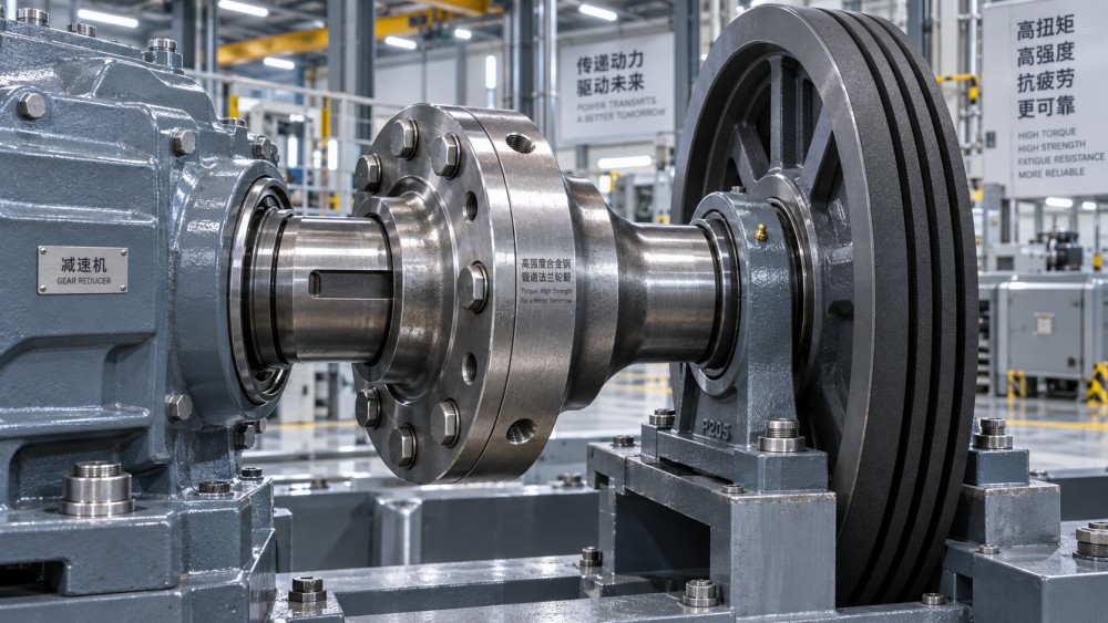
Many hubs are installed close to bearings, pulleys, sprockets, gears, brake discs, or impellers. That arrangement can introduce bending through the shaft-hub connection. An overhung pulley, for example, creates radial load that bends the shaft and changes the contact pressure around the bore. If torque is transmitted at the same time, the hub experiences combined torsional and bending stress rather than a simple torsion case.
This is where a component that seems oversized by torque calculation can still develop trouble around the bore or flange. Shaft deflection, poor bearing spacing, or a hub mounted too far from support points can amplify local stress. The design review should therefore include the surrounding assembly: shaft diameter, bearing position, hub face location, pulley or gear offset, and whether the connected component can impose moments during operation.
Shock loading deserves similar attention. Crushers, mixers, rolling equipment, excavating machinery, material-handling systems, and some reciprocating machines can deliver short torque spikes that are difficult to estimate from motor power alone. A torque limiter may reduce risk, but it does not erase the need to understand what happens before the protection device reacts. Where shock is credible, the hub material needs adequate toughness as well as strength, and geometric transitions need to be generous enough to avoid acting as crack starters.
Stress Concentration Usually Decides Where a Crack Begins
Fatigue failures seldom start in the middle of a smooth, well-supported section. They begin where nominal stress is intensified by shape, surface condition, local damage, or assembly effects. A keyway is a familiar example. It reduces cross-section, interrupts load flow, and introduces corners that need careful geometry and machining. A spline can distribute torque more effectively than a single key in some applications, but spline-root form, fit, contact distribution, and fretting behavior become critical.
The same principle applies to flanged hubs. Bolt holes positioned too close to a transition, abrupt changes in wall thickness, narrow fillet radii, and machining marks running across the principal stress direction can all reduce fatigue margin. A forged blank does not compensate for poor final geometry. In fact, the higher the intended service load, the less acceptable it is to treat fillet radii, keyway finish, or bore surface condition as minor drawing details.
Technical teams should review the finished part rather than only the forging shape. Ask for the machining drawing, tolerance scheme, surface-finish requirements where fatigue is relevant, and the intended relationship between the bore, keyway, flange, and forged grain direction. If the supplier cannot explain why a particular transition is shaped as it is, that is worth investigating before release.
Grain Flow, Material Cleanliness, and Heat Treatment Are Connected
The advantage of a properly engineered forging is not simply that it has been compressed into shape. Forging can refine the internal structure and direct grain flow around the component form, helping the part resist load paths that would otherwise cross a less favorable structure. This benefit is strongest when the forging route, reduction, die design, and machining allowance are appropriate for the finished hub geometry.
For a critical hub, material selection should not stop at a general steel grade name. Chemical composition, inclusion content, segregation control, and the consistency of incoming bar or billet material can all influence fatigue behavior. Non-metallic inclusions and internal discontinuities may become initiation points under high-cycle loading. The appropriate level of material control depends on the consequence of failure and the service severity, but traceability should be proportionate to the risk.
Heat treatment is another common source of misunderstanding. Higher hardness may improve wear resistance or strength, yet it can reduce toughness if the process is not selected for the loading environment. A hub exposed to shock, low-temperature service, or substantial stress concentration needs a balanced property profile rather than a hardness target pursued in isolation. The evaluator should confirm the specified mechanical properties, heat-treatment condition, hardness test locations where relevant, and whether those requirements apply to the finished section thickness.
Temperature, Corrosion, and Fretting Can Reduce the Available Margin
The material properties used in a room-temperature calculation may not represent service conditions. Elevated temperature can alter strength and relaxation behavior; low temperature can make toughness more important. In process equipment, hot environments may also affect nearby lubrication and seals, increasing vibration or misalignment over time. The hub itself may not be the original thermal problem, but it will see the consequences.
Corrosion is equally easy to underestimate. A surface pit is a stress raiser. In wet, chemical, marine, or outdoor environments, coating choice, drainage, sealing, and inspection access become part of fatigue management. This is particularly relevant for equipment connected to water infrastructure, pumps, valve drives, and outdoor power transmission systems. Coating cannot rescue an unsuitable material or poor geometry, but neglecting corrosion protection can shorten the useful life of an otherwise competent hub.
Fretting deserves a direct mention. Small cyclic movement between the bore and shaft, between spline flanks, or beneath a clamped interface can produce oxidized wear debris and surface damage. It often points to insufficient interference, inadequate clamping, misalignment, poor fit control, or a load path that was not anticipated. A hub may pass dimensional inspection and still fret in service if the assembly procedure is vague or the mating shaft is outside the intended tolerance condition.
Inspection Should Match the Failure Consequence
Not every forged hub needs the same inspection package. A lightly loaded replacement component does not justify the same controls as a hub in a safety-sensitive or high-downtime drive. The mistake is treating inspection as a generic checkbox rather than linking it to the likely failure modes.
Dimensional inspection is essential because bore size, runout, concentricity, flange flatness, keyway position, and fit tolerances affect assembly load distribution. For more demanding applications, the agreed scope may also include non-destructive examination suited to the geometry and risk, alongside material and heat-treatment documentation. The method, acceptance criteria, inspection stage, and sampling approach should be defined in the purchase documentation rather than left to assumption.
A practical point from supplier evaluation: ask whether inspection occurs before or after final machining. A discontinuity exposed during machining may not be visible in an earlier inspection state. Conversely, some checks are more meaningful before coating or assembly. The right sequence depends on the part and the specified control plan, but the sequence should be understandable.
What to Put in a Technical Enquiry Before Selecting a Supplier
The best supplier cannot compensate for an incomplete enquiry. For forged hubs for industrial equipment, provide the assembly drawing where possible, not just the hub outline. State the shaft interface, connection method, rotating speed, normal and peak torque assumptions, reversal frequency, radial or axial loads, operating temperature, environment, and expected maintenance access. If failure would stop a production line, damage a gearbox, or create a safety concern, say so. That context affects material recommendations, forging route, inspection depth, and commercial lead time.
Also distinguish between dimensions that are functionally critical and those that are merely convenient to hold tightly. Excessively restrictive tolerances can increase cost and lead time without improving fatigue life. At the same time, relaxed bore or keyway tolerances in a high-load fit can create a far more expensive service issue later. Good evaluation is about putting control where the physics requires it.
This is the kind of cross-functional review that Global Industrial Machining & Piping Equipment Network (IMPE) is designed to support: connecting forging metallurgy, machining capability, power transmission behavior, inspection evidence, and installation realities. A hub is a relatively compact part, but its reliability is determined by the full system around it.
The Sensible Selection Decision
Select a forged hub on the basis of its actual duty, not its appearance or a single headline rating. The priority factors are cyclic and reversing torque, shock exposure, combined bending, local stress concentration, material integrity, heat-treatment balance, environmental effects, and fit quality. If these factors are well defined, a supplier can propose a hub with a defensible manufacturing and inspection route. If they are not, even a high-quality forging becomes an engineering guess.
Before release, examine the load spectrum, the shaft-hub interface, and the transitions where fatigue cracks are most likely to begin. That review usually reveals whether the proposed component is genuinely suited to the machine—or merely capable of fitting on it.
Related News
- How to Assess a Rigid Coupling Supplier for Bore Accuracy and Traceable QualityOct 08, 2026Tribology & Kinematics Expert
- Titanium Alloys Compared: Balancing Strength, Corrosion Resistance, and MachinabilityOct 08, 2026CNC Kinematics Architect
- Where Ductile Iron Dismantling Joints Reduce Alignment Risk in Water PipelinesOct 08, 2026Pipeline Metallurgy Scientist
- Selecting a Precision Bearing Sleeve: Fits, Runout, and Material ChoicesOct 08, 2026Tribology & Kinematics Expert
- Face Milling Cutters: How Insert Geometry Affects Finish on Steel and AluminumOct 08, 2026CNC Kinematics Architect
- Single-Acting Cylinders for Clamping: Stroke, Force, and Return Spring ConsiderationsOct 07, 2026Fluid Power Control Strategist