
Custom Forged Flanges: Specification and Inspection Requirements for Pressure Piping
Custom forged flanges are pressure-boundary components, not merely connection hardware. In a water transmission line, refinery utility system, process skid, high-pressure hydraulic circuit, or power-generation piping run, the flange must maintain a reliable seal while carrying pressure, bolt load, temperature effects, vibration, and sometimes corrosion. When a flange is made outside a standard catalog range—because of unusual bore geometry, a non-standard hub, special drilling, high design pressure, or a project-specific material—the normal purchasing shortcut of “same nominal size and pressure class” is no longer enough.
For quality and safety teams, the central question is simple: can the supplied flange be demonstrated to match the design basis and remain fit for the intended service? That answer depends on more than a dimensional check at final inspection. It begins with the purchase specification, follows the material through forging and heat treatment, and ends with a documented review of machining, examination, marking, and release records.
A Custom Flange Needs a Defined Technical Baseline
The term custom forged flanges covers a wide range of products. A forged weld-neck flange with a modified bore is very different from a blind flange with a special bolt circle or an integral flange forged as part of a nozzle. The inspection plan should therefore be tied to the actual pressure-boundary design, not to a generic flange checklist.
A workable specification normally identifies the governing piping code, design pressure and temperature, flange type, facing, dimensions, material grade, heat-treatment condition, and required documentation. In many international projects, ASME B16.5 or ASME B16.47 is relevant for standard dimensional ranges, while ASME B31.3, B31.1, or another applicable piping code may govern the system design and acceptance philosophy. ASTM material specifications are commonly used to define forged carbon steel, alloy steel, and stainless steel flange materials. None of these references should be assumed automatically: the project specification must state which editions, supplements, and purchaser requirements apply.
This becomes especially important when a drawing departs from a published standard. A flange may retain the bolt pattern of a standard class but use a thicker hub, a non-standard bore, or a different facing detail. Once geometry changes, the supplier and purchaser need a clear engineering basis for pressure performance, bolt loading, gasket compatibility, and weld-end configuration. Calling it “equivalent to Class 300” without defining the deviations is a common source of confusion during inspection and later during installation.
Material Selection Is About the Service Envelope
The material designation on a purchase order is only the starting point. Carbon steel forgings may be suitable for many ambient and moderately elevated-temperature services, but low-temperature duty can trigger impact-testing requirements. Stainless and alloy steels may be selected for corrosion resistance, elevated temperature, or particular process fluids, yet they introduce their own controls around chemistry, heat treatment, sensitization risk, hardness, and positive material identification.
Quality personnel should be wary of material substitutions described as “higher grade” without engineering approval. Higher tensile strength does not automatically mean better flange performance. The substitution may alter weldability, toughness, corrosion behavior, allowable stress basis, or compatibility with adjoining pipe and fittings. A material change should be controlled through the project’s technical query or deviation process, with the relevant design authority involved.
Forging is specified for good reason in critical applications. Proper deformation and controlled reduction can improve continuity of the material structure compared with a component made from less suitable stock. But “forged” is not a blanket assurance of soundness. Starting stock quality, forging practice, heat treatment, machining allowance, and examination coverage still determine whether a finished flange is acceptable.
What the Purchase Specification Should Make Unambiguous
A good flange specification removes ambiguity before production begins. This matters most where custom geometry makes visual comparison with a catalog item impossible. At minimum, the controlled package should include an approved drawing with revision status, material specification, applicable dimensional standard where relevant, pressure-temperature design data, facing requirements, and marking instructions.
The following controls often deserve explicit treatment rather than being left to supplier practice:
- Required forging route and any restrictions on welded repairs, weld buildup, or material blending.
- Heat-treatment condition, including whether normalizing, quenching and tempering, solution annealing, or stress relief is required by the material specification or project documents.
- Mechanical test requirements, test location, and whether impact testing applies at the minimum design metal temperature.
- Non-destructive examination method, examination area, acceptance criteria, and personnel qualification requirements.
- Dimensional tolerances for non-standard features, including bore transitions, hub profile, bolt holes, facing finish, and weld-end preparation.
- Traceability, material test reports, inspection hold points, third-party witness requirements, preservation, and shipment protection.
The phrase “NDE required” is not sufficient. Magnetic particle testing, liquid penetrant testing, ultrasonic testing, and radiographic examination detect different types of discontinuities and have different limitations. Surface-breaking indications may be addressed by MT or PT depending on material and surface condition. UT is often useful for internal discontinuities in a suitably shaped forging, but coverage and sensitivity depend on access, geometry, grain structure, and approved procedure. The method must fit the component and the risk being controlled.
Traceability Cannot Be Reconstructed at Final Release
For pressure piping, traceability should survive every value-adding step: receipt of raw material, cutting, forging, heat treatment, rough machining, final machining, testing, marking, and packing. The practical goal is to connect each finished flange to its heat or lot, material certificate, heat-treatment record, test results, and inspection status without relying on memory or paperwork assembled after the fact.
A material test report should be reviewed for more than a matching grade name. Verify the heat number, chemical analysis, mechanical properties, heat-treatment condition where applicable, and consistency with the ordered material specification. If the project requires supplementary testing, that requirement should appear in the traceable record. When the flange is machined from a larger forged blank, the documentation should also make clear how the final part relates to the tested lot.
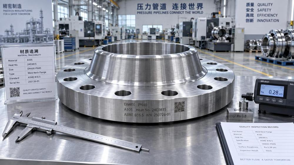
Marking is part of this control. Permanent identification should remain legible but must not damage a stressed or sealing surface. Deep stamping in an unsuitable location, for example, can create an avoidable stress raiser. The drawing or quality plan should state where marking is permitted and whether low-stress stamping, vibro-etching, or a tag-based method is acceptable. The required content often includes manufacturer identification, material grade, pressure designation where applicable, size, heat or traceability number, and relevant standard references.
Dimensional Inspection: The Sealing Face Deserves Extra Attention
A flange can possess valid material certificates and still create a leak path if machining control is poor. For custom parts, inspection should compare the finished component directly with the latest approved drawing, not with a similar item on the shop floor. This sounds obvious, yet drawing revision errors are a recurring real-world risk when a manufacturer handles closely related flange families.
The critical dimensions usually include outside diameter, thickness, bore, hub dimensions, bolt-hole quantity and position, bolt-circle diameter, facing geometry, and weld-end details. Flatness and face runout matter because gasket compression is rarely forgiving of a distorted or eccentric flange. For raised-face, ring-type joint, tongue-and-groove, or other special facings, the inspection method must match the profile and finish specified for the gasket system.
Surface finish should not be treated as a cosmetic requirement. The required roughness and machining pattern are linked to gasket type and sealing design. A face polished beyond the intended condition is not automatically better; some gasket arrangements rely on a controlled surface texture to achieve stable sealing. Conversely, chatter marks, radial scoring, dents, corrosion pits, or handling damage on the gasket seating area can justify rejection even if basic dimensions are within tolerance.
Machining and NDE Should Be Sequenced Intentionally
Inspection timing affects what can actually be found. A rough-forged surface may be appropriate for an early examination intended to reveal laps or gross surface discontinuities. Final machining can expose defects that were previously hidden beneath scale or excess stock. For this reason, a quality plan may require examination at more than one stage, particularly on high-consequence parts.
The acceptance standard must be agreed in advance. Inspectors should not be asked to make subjective decisions based only on whether an indication “looks minor.” Applicable material specifications, purchaser requirements, and approved NDE procedures should define acceptance. If a nonconformance is found, repair is not a routine shop decision. Any proposed blending, weld repair, re-heat treatment, or re-examination needs formal disposition according to the governing specification and project controls.
A Practical Inspection Release Review
Before release, the inspector is effectively confirming that the physical flange, the design requirement, and the document package tell the same story. A concise review is often more effective than a long generic checklist when it focuses on the failure points most likely to affect safe service.
Packaging is also worth checking. Finished flange faces should be protected against impact and moisture during transport and storage. A compliant inspection report does little good if the raised face is damaged by metal-to-metal contact before installation. For stainless materials, handling and storage controls should also limit contamination from carbon steel tools, racks, or debris where corrosion performance is a concern.
The Installation Interface Is Part of the Safety Decision
Even a fully conforming forged flange can fail in service because of an interface problem: incorrect gasket selection, mixed flange facings, unsuitable bolting, poor alignment, excessive piping loads, or uncontrolled bolt tightening. Quality release should not be mistaken for system readiness. The installation team needs the approved assembly requirements, including compatible gasket and bolting information, torque or tensioning procedure where specified, and any limitations on flange rotation or alignment.
This is particularly relevant in fabricated spools and equipment nozzles. A weld-neck flange can be dimensionally correct before welding but distorted afterward by poor fit-up or uncontrolled heat input. Post-weld checks should therefore be planned when flange alignment, facing condition, or nozzle orientation could be affected. The same thinking applies to heavy piping, where unsupported loads and misalignment can place unintended bending stress into a bolted joint.
For organizations managing diverse piping, machining, casting, and fluid-power supply chains, the useful discipline is to treat custom forged flanges as engineered pressure components with a traceable manufacturing history. The strongest release decision is not based on a single certificate or a visual pass. It comes from a consistent chain: defined design intent, verified material, controlled forging and heat treatment, appropriate examination, accurate machining, protected delivery, and an installation interface that has been checked rather than assumed.
Related News
- How to Assess a Rigid Coupling Supplier for Bore Accuracy and Traceable QualityOct 08, 2026Tribology & Kinematics Expert
- Titanium Alloys Compared: Balancing Strength, Corrosion Resistance, and MachinabilityOct 08, 2026CNC Kinematics Architect
- Where Ductile Iron Dismantling Joints Reduce Alignment Risk in Water PipelinesOct 08, 2026Pipeline Metallurgy Scientist
- Selecting a Precision Bearing Sleeve: Fits, Runout, and Material ChoicesOct 08, 2026Tribology & Kinematics Expert
- Face Milling Cutters: How Insert Geometry Affects Finish on Steel and AluminumOct 08, 2026CNC Kinematics Architect
- Single-Acting Cylinders for Clamping: Stroke, Force, and Return Spring ConsiderationsOct 07, 2026Fluid Power Control Strategist