
Sizing Tie-Rod Cylinders for Industrial Presses: Force, Stroke, and Cycle-Life Factors
Start with the force required at the point where the press is doing its hardest work, then size the tie-rod cylinder around the full mechanical and hydraulic duty. A cylinder that reaches a nominal tonnage on paper can still be unsuitable if pressure drops during fast advance, the rod becomes unstable near full extension, or the press frame introduces side load. The usable specification must connect the workpiece, tooling, press structure, hydraulic circuit, and production cycle.
For industrial presses, the correct cylinder is defined by its minimum available force at the required operating pressure, its working stroke, rod stability, retraction force, mounting arrangement, and expected number of loaded cycles. Catalog bore size is only one result of that assessment.
Establish the force requirement at the ram
Press force should be based on the actual resistance of the operation rather than the capacity of a previous machine or a broad estimate of material strength. Blanking, coining, bending, deep drawing, compression molding, press fitting, and bonded assembly create very different load curves. Some processes require a sharp peak at the end of travel; others need a sustained load while material flows or an adhesive cures. A cylinder selected for a brief peak may overheat or suffer seal distress when asked to hold near maximum pressure for long dwell periods.
The basic hydraulic relationship is:
Force = Pressure x Effective Piston Area
For extension, effective area is the full piston area. On retraction, the rod occupies part of that area, so available pull force is lower. This difference matters where the return stroke must strip a formed part from a die, retract a guided platen against springs, or pull tooling clear of compacted material. A double-acting cylinder should therefore be evaluated in both directions rather than being described only by its extension tonnage.
Use the pressure that the power unit can maintain at the cylinder port during the demanding portion of the cycle. Relief-valve setting is not automatically the working pressure. Pressure losses through directional valves, proportional valves, manifolds, filters, hoses, quick couplings, and undersized pipework reduce pressure at the actuator. Losses become more pronounced during high-flow movement, especially when a long cylinder is fed through restrictive fittings.
The calculated process load also needs a justified allowance for friction, tooling condition, material variation, misalignment, and startup conditions. The allowance should not conceal uncertainty in the forming calculation or tool design. An excessively large cylinder may create a different problem: the press frame, bolster, die set, fasteners, and safety devices can be exposed to forces beyond their intended rating. Size the actuator to deliver the required controlled load, and make sure the hydraulic circuit limits the maximum available force to the structural capacity of the entire press.
Force is not constant through the cycle
A load-versus-stroke profile is more useful than one maximum number. During approach, the ram may need only enough force to overcome seal friction and move tooling. Contact with the workpiece changes the demand. Near bottom dead center, coining or final seating may produce the highest pressure. During return, vacuum effects, part adhesion, die springs, and ejectors can create a separate pull-load requirement.
This profile affects cylinder choice and circuit design. A large bore has greater fluid volume and can slow the approach unless pump flow is increased. A regenerative circuit, a prefill valve, or a two-speed arrangement may allow rapid low-force advance followed by slower high-force pressing. These approaches require careful control because a regenerative connection changes the effective area and therefore reduces extension force. Quoting the full-bore force while the circuit is in regeneration leads to an incorrect press-capacity assumption.
Choose bore and system pressure together
Higher pressure permits a smaller bore for the same thrust, but it is not automatically the better arrangement. A smaller cylinder can reduce oil volume, response lag, mounting space, and moving mass. It also places greater demand on seals, hose assemblies, valve ratings, surface finish, contamination control, and pressure management. Pressure spikes caused by abrupt deceleration or trapped oil can become proportionally more severe in a high-pressure design.
A larger bore produces the required force at lower pressure, which can provide useful control margin where pump pressure fluctuates. Its tradeoffs include more fluid displacement, a larger mounting envelope, potentially higher rod compression load, and slower motion if the existing pump flow remains unchanged. The practical selection is usually the bore-pressure combination that achieves the force profile while fitting the press structure and available flow, not the smallest possible cylinder.
Pressure capability should be verified across the complete assembly. Cylinder tube, end caps, tie rods, piston, rod, gland, port threads, fittings, hoses, and valves all need compatible ratings. A cylinder may be rated for a pressure that the attached hose, compact manifold, or pressure transducer cannot tolerate. The selected relief setting, pressure intensification risk, and any accumulator discharge condition must be documented on the circuit information used for final sizing.
Stroke is a usable travel requirement, not an overall length
Required stroke begins with the open height needed to load material, position the workpiece, clear the tooling, and remove the finished part. Add the actual forming or assembly travel, then account for required overtravel, adjustable stops, die wear, and any cushion or ejector movement that affects the ram position. The cylinder must reach the end of the productive movement without being used as the mechanical stop.
Bottoming a hydraulic cylinder against its internal end cap can transmit impact through the piston, rod, gland, mounting, and press frame. End-of-stroke cushions reduce deceleration energy but do not replace positive external stops where accurate press closure is required. If a hard stop establishes final part thickness or tooling position, the hydraulic control must limit pressure and dwell without forcing the cylinder farther after the stop is reached.
A longer stroke also changes the mechanical problem. As the rod extends, the unsupported compression length increases and buckling resistance falls. The force that is harmless at a short projection can be unsafe at full extension. Cylinder stroke should therefore be evaluated alongside the distance between rod support points, platen guidance, mounting type, and load direction.
Rod diameter and mounting determine whether the cylinder remains stable
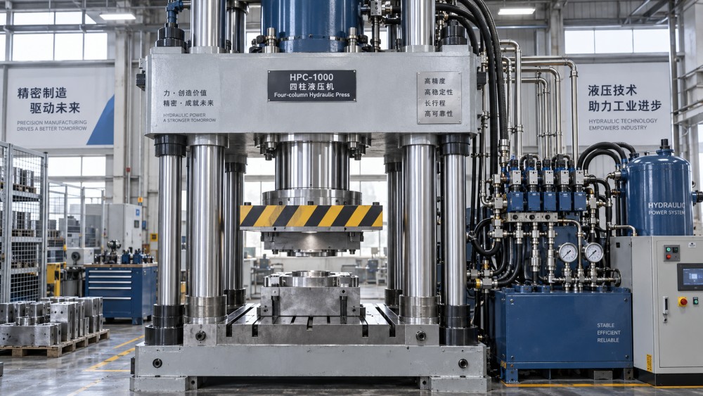
Industrial press cylinders primarily work in compression during the pressing stroke. The rod must resist buckling under the highest compressive load at the most unfavorable extension. Rod selection cannot be separated from the way the cylinder is mounted. A rigid flange-mounted cylinder driving a well-guided platen has a different effective column length from a clevis-mounted cylinder with pivoting ends.
Mounting geometry should allow the cylinder to follow the press motion without being asked to correct frame error. Centerline offset between the cylinder and the ram, uneven guide wear, tilted platens, or deflecting tooling can impose side load on the rod and gland. The visible symptom may be premature rod-seal leakage, but the root cause can be platen misalignment rather than poor seal material. Replacing seals without correcting the load path leaves the failure mechanism in place.
For a fixed-direction pressing application, flange mounting near the cylinder centerline commonly offers a stiff load path. Clevis, trunnion, and spherical arrangements are useful where the machine motion requires angular movement, provided the associated linkages and pins are sized for the load. A pivoting mount should not be used simply to accommodate an inadequately guided press ram. The platen needs guides designed to absorb lateral force; a tie-rod cylinder is an actuator, not a linear guide.
Tie rods and end caps deserve the same attention as the piston rod. High tensile loading, repeated pressure cycling, loose nuts, uneven tightening, or frame distortion can affect end-cap sealing and structural integrity. The cylinder drawing should state the mounting face, thread or bolt pattern, port orientation, rod-end connection, closed and extended dimensions, and the permitted load direction. Ambiguity in any of these items can produce a cylinder that has the correct force but cannot be installed or aligned.
Match flow to the required cycle, then examine heat
Stroke time follows the displaced oil volume and delivered flow. For extension, required flow is piston area multiplied by target rod speed. Retraction uses the annular area, so the same pump flow produces a different speed. This is particularly relevant when a fast return is expected from a cylinder with a large rod, or when a slow controlled closing speed is needed after a rapid approach.
Nominal pump displacement is not enough to predict motion. Actual flow at the cylinder changes with pump efficiency, pressure, oil temperature, valve metering, internal leakage, and parallel consumers. Long small-diameter lines add both pressure drop and compliance; the ram can hesitate or overshoot when compressed fluid volume is released. A large cylinder connected through restrictive plumbing may meet the force calculation yet fail the production timing requirement.
Cycle rate also determines thermal load. Every pressure drop across a throttling valve becomes heat, and repetitive cushioning adds heat near the end of travel. A cylinder repeatedly held at pressure can generate leakage heat even when it is not moving. Fluid temperature affects viscosity, which influences leakage, valve response, lubricity, and seal behavior. Size the actuator together with the circuit strategy: controlled meter-out motion, load-holding valves, prefill arrangements, and cooling capacity all alter stable press operation.
Cycle life begins with the load spectrum
Cycle-life assessment should distinguish occasional peak force from the force used repeatedly. A press that runs thousands of modest strokes with a short high-load finish has a different duty from one that holds close to maximum pressure on every cycle. Dwell time, reversal frequency, travel speed, ambient temperature, and contamination level influence seal wear, rod finish preservation, bearing load, and fatigue exposure.
The cylinder specification should identify the expected cycle pattern: strokes per operating period, extension and retraction speeds, loaded portion of travel, maximum pressure duration, and whether pressure reverses while the tool is in contact. This information allows seal selection and cushioning to be matched to the motion instead of treating a cylinder as a static force device.
Seal material must suit the hydraulic fluid, temperature range, pressure, and sliding speed. A seal optimized for low friction may not be the preferred choice for a high-pressure holding application with contaminated fluid. Wear rings or bearing bands keep metal surfaces separated and stabilize the piston under side loading; their condition can strongly influence bore scoring and internal bypass. Rod wipers matter wherever scale, abrasive dust, coolant residue, or fine metal particles are present around the press.
Rod surface condition is equally important. Scratches, corrosion pits, damaged chrome, or contamination trapped at the wiper can rapidly damage a rod seal. Protective boots can reduce environmental exposure, but they need inspection because trapped debris or moisture can create a hidden corrosion zone. Where external rod protection is not feasible, specify suitable surface treatment and establish cleaning practices around die-change and maintenance work.
Specify the press-cylinder interface before release
Reliable selection depends on a complete interface record rather than a short request for “a cylinder of a given tonnage.” The record should include the required force profile, available pressure at the actuator, bore and rod dimensions, stroke and mechanical stops, port sizes, mounting drawing, rod-end connection, allowed side load, duty cycle, fluid type, temperature range, and space claim for service access.
- Press load path: show where force enters the platen, where guides react side load, and whether eccentric tooling creates a moment across the ram.
- Control behavior: identify whether the press needs simple extend-retract motion, controlled speed transitions, pressure holding, position feedback, or synchronized movement with another cylinder.
- Maintenance clearance: retain enough room to disconnect hoses, remove the gland or rod assembly where the design permits, and inspect tie-rod nuts without dismantling unrelated press components.
- Verification points: define where pressure is measured, how ram travel is confirmed, and which mechanical stops prevent an overtravel event during commissioning.
For synchronized multi-cylinder presses, cylinder sizing alone cannot guarantee even loading. Small differences in friction, trapped air, hose length, valve characteristics, or structural stiffness can cause one ram corner to lead. Position feedback, flow division, mechanical guidance, and a sufficiently stiff platen may all be necessary. Treating four equal cylinders as four identical force sources can result in uneven tooling load and accelerated guide wear.
The final selection should show that force remains available at the working point, the rod is stable at maximum extension, the mounting transfers load without side thrust, and the hydraulic circuit can achieve the required motion without excessive pressure loss or heat. Those conditions turn a nominal cylinder capacity into dependable press performance over its intended service life.
Related News
- How to Assess a Rigid Coupling Supplier for Bore Accuracy and Traceable QualityOct 08, 2026Tribology & Kinematics Expert
- Titanium Alloys Compared: Balancing Strength, Corrosion Resistance, and MachinabilityOct 08, 2026CNC Kinematics Architect
- Where Ductile Iron Dismantling Joints Reduce Alignment Risk in Water PipelinesOct 08, 2026Pipeline Metallurgy Scientist
- Selecting a Precision Bearing Sleeve: Fits, Runout, and Material ChoicesOct 08, 2026Tribology & Kinematics Expert
- Face Milling Cutters: How Insert Geometry Affects Finish on Steel and AluminumOct 08, 2026CNC Kinematics Architect
- Single-Acting Cylinders for Clamping: Stroke, Force, and Return Spring ConsiderationsOct 07, 2026Fluid Power Control Strategist