
Sizing Hydraulic Reservoirs for Power Units to Control Heat, Aeration, and Downtime
Reservoir sizing should begin with the heat balance and the pump inlet condition, not with a fixed tank-to-flow rule. A hydraulic power unit can have a large tank and still run hot if its surfaces cannot reject the generated heat. It can also have enough nominal volume yet suffer from foaming, cavitation noise, unstable actuator motion, and repeated filter blockage when return flow enters too close to the suction zone.
The reservoir must provide usable oil volume, free surface area, air-release time, contaminant settling space, and a stable supply to the pump. Those functions compete for the same physical envelope. A compact power unit serving a short, intermittent cylinder cycle has very different needs from a continuously operating press, a mobile machine exposed to changing ambient temperatures, or a central unit feeding multiple valve stations.
Start with the duty cycle, not pump displacement alone
Pump flow is important, but it is only one input to reservoir capacity. A pump may deliver high flow for short motion periods and spend much of the shift unloaded or stopped. Another unit may circulate moderate flow continuously through proportional valves, throttling restrictions, and long pipe runs. The second system can impose a higher thermal burden despite a lower rated flow.
Build the sizing basis from the expected operating cycle: flow rate during each mode, pressure in each mode, duration, idle time, ambient temperature, and the likely simultaneous movements. Include losses from pressure-reducing valves, relief valves, flow controls, long undersized return lines, and components that deliberately convert hydraulic energy into heat. A reservoir cannot correct an inefficient circuit; it only absorbs heat for a period and releases some of it to the surroundings.
Reservoir volume also changes during operation. Single-rod cylinders transfer a meaningful volume of oil between the tank and the cylinder as the rod extends and retracts. Accumulators, drain lines, leakage returns, and maintenance fill levels further affect the working liquid level. The low level must remain above the suction connection with enough submergence to prevent vortex formation, while the high level must leave expansion space and room for return-flow turbulence to settle below the breather area.
Separate thermal storage from continuous cooling
A reservoir has thermal mass. During a short, intense work cycle, that mass can delay the oil-temperature rise. This can be useful where the unit has long recovery periods. It should not be mistaken for permanent cooling capacity. Once heat input exceeds heat rejection over repeated cycles, oil temperature continues to rise until a new equilibrium is reached or the system is shut down.
Heat rejection depends on exposed tank area, material, wall thickness, surface condition, air movement, installation clearance, and the temperature difference between oil and ambient air. A painted steel reservoir mounted in open air behaves differently from the same tank enclosed in a sound-insulated cabinet or installed beside a furnace. Stainless steel and aluminum designs also require separate review of structural stiffness, weld practice, corrosion environment, and heat-transfer behavior rather than assuming a material substitution preserves all performance.
Where the operating profile produces sustained losses, establish a heat balance before finalizing the tank envelope. The required cooling method may be a larger reservoir, a forced-air oil cooler, a water-cooled exchanger, reduced throttling loss, a variable-speed pump strategy, or a circuit revision. Often, a combination is required. Increasing tank volume without confirming the steady-state heat path can consume floor space and oil volume while leaving the underlying overheating problem unchanged.
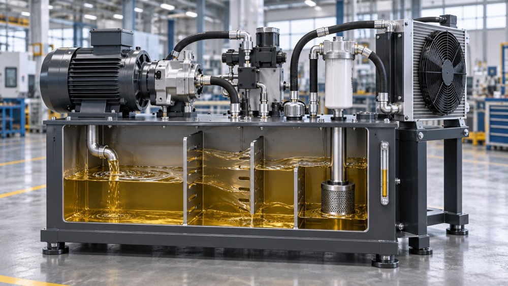
Oil temperature should be evaluated at the stabilized operating condition rather than immediately after startup. Cold oil can hide insufficient cooling because its viscosity is high and its initial temperature is low. Conversely, a system that appears hot during commissioning may be reacting to an incorrectly set relief valve, a bypassing directional valve, a cooler with no effective airflow, or a return line that is creating excessive backpressure. These faults need correction before reservoir volume is treated as the cause.
Give entrained air time and distance to leave the oil
Air enters hydraulic fluid through suction-side leaks, returning cylinder oil, inadequate fluid level, turbulent return discharge, and mechanical agitation within the tank. Entrained air reduces effective bulk modulus, makes servo or proportional control less stable, accelerates oxidation, and can contribute to pump damage when bubbles collapse in high-pressure zones. Surface foam is visible, but harmful dissolved or finely entrained air may be present before a thick foam layer appears.
Residence time matters because bubbles need a relatively calm fluid path to rise and separate. Nominal tank volume is not equal to effective residence volume. If incoming return oil travels directly toward the suction connection, much of the tank can be bypassed hydraulically. A large but poorly partitioned reservoir can therefore perform like a much smaller one.
Arrange the main return outlet away from the pump suction pickup and below the minimum oil level. The discharge should not strike the tank wall or fluid surface at high velocity. Diffusers can reduce jet energy, but their design must avoid excessive backpressure and must remain accessible for inspection. Directing return flow through a suitable internal path encourages circulation through the reservoir instead of allowing a short route between return and suction.
Baffles are useful when they create a longer, quieter flow path and isolate the pump suction zone from return turbulence. They are less useful when treated as a generic plate installed wherever fabrication is easiest. The baffle height, bottom clearance, openings, and relationship to the fluid level all influence circulation. A full-height barrier with no deliberate flow path can create stagnant regions; a low or badly positioned plate may do little to prevent short-circuiting.
Common air-related symptoms do not all point to the same defect
- Foam around the filler or breather often indicates return-line agitation, an overfilled tank, incompatible fluid additives, or water contamination. It does not automatically prove that the reservoir is undersized.
- Growling or gravel-like pump noise after startup is more consistent with inlet restriction, low oil level, excessive viscosity, a blocked suction strainer, or an air leak on the suction side.
- Jerky cylinder motion after extended operation can result from entrained air, but also from stick-slip at seals, unstable load conditions, valve hysteresis, or insufficient pressure margin.
- Rapidly rising fluid temperature calls for a circuit-loss review before simply increasing capacity. A relief valve passing flow continuously can overwhelm a reservoir of almost any practical size.
Protect the pump inlet under all fluid-level conditions
The suction connection is one of the most consequential details in a power-unit reservoir. Its location must provide adequate liquid head at the lowest permitted operating level, including cylinder displacement and expected oil contraction or expansion. It should be separated from return turbulence and positioned so sediment at the tank bottom is not drawn directly into the pump.
A suction line that is too small, too long, or crowded with restrictive fittings raises inlet losses. Fine suction filtration is especially risky unless the pump supplier specifically allows it and the pressure drop is assessed across the full viscosity range. A coarse suction strainer can protect against large debris during commissioning, but it is not a substitute for clean assembly, effective return filtration, and controlled filling. Restriction at the inlet may produce cavitation even when the reservoir itself appears adequately sized.
For installations at elevation, in cold locations, or with high-viscosity fluid, available inlet pressure requires closer review. The pump’s inlet requirement must be considered alongside atmospheric pressure, static oil head, line losses, fluid vapor pressure, and any pressurization of the tank. A reservoir cover that is sealed too tightly can create vacuum as the oil level falls. A breather that admits unfiltered humid air creates a different problem: moisture contamination and accelerated fluid degradation.
Capacity must include real operating volume
Do not specify a tank solely by its external dimensions or gross catalog capacity. Define the normal fill level, low operating level, maximum level, expansion allowance, cylinder differential volume, and unusable volume below the suction-safe level. These values produce the usable fluid capacity. A tank that appears generous on a general arrangement drawing can become marginal once internal baffles, immersion heaters, level switches, return diffusers, suction hardware, and a service access zone are included.
Tank geometry and fabrication details affect field performance
A long, shallow tank provides broad surface area and can support a longer internal flow path, but it requires enough footprint and may be sensitive to low-level conditions during machine motion. A tall, narrow tank saves floor space but may offer less natural heat dissipation and can concentrate return turbulence near the suction zone if ports are poorly arranged. The selected shape should follow the available installation envelope, service access, heat-rejection requirement, and oil-level range.
Internal surfaces need fabrication quality appropriate for a fluid-cleanliness system. Weld spatter, scale, loose coating, grinding residue, and trapped blasting media can contaminate the circuit at startup. Welded baffles and mounting pads should be placed so that internal areas remain cleanable and drainable. Corners that retain sludge, inaccessible cavities, and fittings that cannot be tightened or inspected after installation create maintenance problems that are expensive to correct once the power unit is assembled.
Return, drain, breather, filler, level gauge, temperature sensor, heater, cooler connections, and cleaning cover locations should be coordinated before fabrication. Case-drain returns from pumps and motors often require special routing because they can carry aerated, warm oil. Sending them into the same high-energy return zone without review may increase aeration. Routing them directly into the suction region is also undesirable. Connection elevations must account for piping loads, vibration isolation, and the need to prevent unintended siphoning during service.
Commissioning should verify the assumptions behind the size
A correctly drawn reservoir can still perform poorly when piping installation changes the intended flow pattern. During commissioning, record fluid temperature through representative cycles, observe the level range, inspect for foam after return flow is established, and listen for pump inlet noise at cold start and after warm-up. Verify that coolers receive the expected air or water flow and that bypass arrangements are not silently returning flow to tank.
Cleanliness should be established before the system enters normal duty. Reservoir flushing, controlled filling through appropriate filtration, inspection of internal surfaces, and post-start filter monitoring are particularly important after field welding or piping modifications. Repeated filter loading shortly after startup may indicate construction debris, but it can also reveal deteriorating hose material, paint contamination, or component wear. Treating every filter alarm as a filter-selection issue delays the real correction.
The final reservoir specification should therefore document more than gross capacity. It should state the usable volume range, expected fluid level at key actuator positions, return and suction port arrangement, baffle intent, thermal design basis, breather arrangement, filtration locations, fluid type and viscosity range, and required inspection access. Those details turn a tank into a controlled part of the hydraulic system rather than an oversized container attached to it.
Related News
- How to Assess a Rigid Coupling Supplier for Bore Accuracy and Traceable QualityOct 08, 2026Tribology & Kinematics Expert
- Titanium Alloys Compared: Balancing Strength, Corrosion Resistance, and MachinabilityOct 08, 2026CNC Kinematics Architect
- Where Ductile Iron Dismantling Joints Reduce Alignment Risk in Water PipelinesOct 08, 2026Pipeline Metallurgy Scientist
- Selecting a Precision Bearing Sleeve: Fits, Runout, and Material ChoicesOct 08, 2026Tribology & Kinematics Expert
- Face Milling Cutters: How Insert Geometry Affects Finish on Steel and AluminumOct 08, 2026CNC Kinematics Architect
- Single-Acting Cylinders for Clamping: Stroke, Force, and Return Spring ConsiderationsOct 07, 2026Fluid Power Control Strategist