
Preventing Side Loads and Seal Failures in Tipping-System Telescopic Cylinders
A telescopic cylinder that begins to weep oil after a few tipping cycles is often treated as a seal problem first. In a tipping system, that can be the wrong starting point. A replacement seal may stop the visible leak briefly, yet fail again because the cylinder is being forced sideways as the body rises or lowers. The seal is then working against a bent rod stage, an out-of-square gland, damaged bearing surfaces, or a load path that the cylinder was never meant to carry.
The practical answer is to control side load at its source before rebuilding the cylinder: verify mounting alignment, tipping-body hinge condition, stage straightness, guide wear, and load distribution. Then inspect the seal system for damage patterns that reveal what happened. For telescopic cylinders for tipping systems, a successful repair is not just replacing soft parts; it is restoring a straight, supported, freely articulating lifting arrangement.
Why side loading becomes a seal failure
A telescopic cylinder is designed primarily for axial compression and extension. During a normal tipping cycle, the cylinder transfers lifting force through its base mount and upper mount while the body pivots around its rear hinges. The cylinder mounts must accommodate the changing angle without binding. Any restriction in that movement creates a lateral force against one side of the cylinder stages.
That force may appear small when the body is empty and operating slowly. Under a loaded body, uneven ground, rapid lowering, or a partially compacted load, the same misalignment can become severe. The extended stages are especially vulnerable because their unsupported length increases as the body approaches a high tipping angle. Instead of sliding concentrically through the guide and seal assembly, a stage presses against one side of the gland. The bearing strip wears unevenly, the seal lip loses stable contact, and hydraulic oil finds a path out.
Side load also accelerates metal damage. A polished chrome surface may develop a bright contact band on one side, longitudinal scoring, or local loss of finish. Once abrasive contamination enters through a damaged wiper or a scored surface, even a correctly sized replacement seal will wear quickly. Repeated seal failure is therefore a diagnostic signal, not merely a parts-consumption issue.
Symptoms that point beyond a normal aging seal
Some leakage is associated with ordinary seal aging, heat exposure, or service life. Side-load-related leakage usually comes with additional clues. The most useful observations are made before cleaning the cylinder completely, because the oil pattern and contact marks can help identify the direction of the problem.
- Oil concentrated on one side of a stage or gland: Leakage that consistently starts from the same side suggests eccentric contact rather than uniform seal deterioration.
- Uneven bearing-strip wear: A guide ring worn thin on one sector, while the opposite sector remains relatively intact, indicates that the stage has been running off-center.
- Polished bands, scoring, or chrome damage: A one-sided polished area may be early rubbing; deep longitudinal marks can cut a new seal immediately during extension.
- Jerky extension or retraction: Stick-slip motion, sudden stage movement, or a cylinder that hesitates at a repeatable body angle may indicate binding in the mounting geometry or internal stage contact.
- Damaged pins, oval pin bores, or distorted brackets: These conditions allow the cylinder to shift off its intended centerline, particularly under load reversal during lowering.
- Leaks return quickly after a rebuild: When correct seals, clean oil, and acceptable assembly practices have already been confirmed, look for a structural cause rather than changing seal material again.
A cylinder can also leak because its relief setting is incorrect, oil is contaminated, or a gland has been assembled improperly. Those issues must be checked, but they do not explain one-sided wear as well as a side-load condition does.
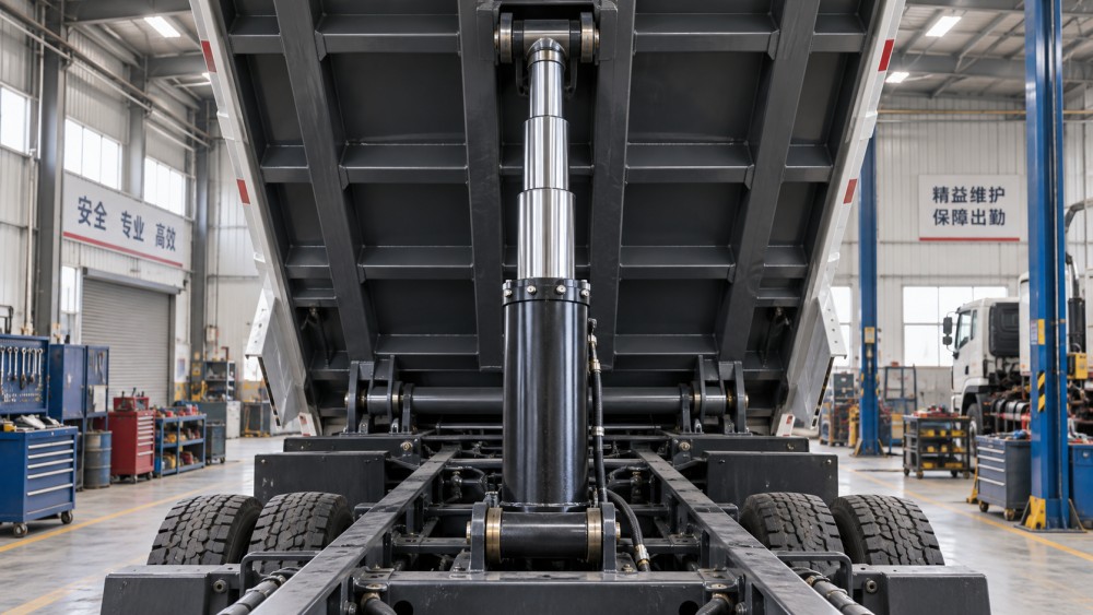
Start the inspection with the tipping mechanism, not the seal kit
Park the vehicle or equipment on firm, level ground and secure it according to the applicable maintenance procedure. A raised body must be supported by approved mechanical props or restraints; hydraulic pressure alone is not a safe support method. Isolate the hydraulic supply, release trapped pressure through the prescribed method, and prevent unintended operation before working around mounts or removing pins.
With the body lowered, inspect the base pivot, upper cylinder connection, rear body hinges, subframe members, and mounting brackets. Look for cracked welds, shifted brackets, loose fasteners, missing spacers, worn spherical bearings, seized bushes, and evidence that a pin has been turning in its bore rather than in its intended bearing surface. Do not judge alignment only by eye from one side of the vehicle. Compare both sides of the body, check whether the cylinder sits centrally between its mounting points, and look for contact marks on nearby structural members.
Then observe the geometry during a controlled empty lift, from a safe position. The cylinder should articulate through the tipping arc without its mounts reaching a hard stop or pulling the barrel sideways. Watch for a sudden change in cylinder angle, bracket movement, or stage deflection as the body approaches a particular position. A fault that occurs only near full extension can be missed during a static inspection with the body down.
Check the rear hinge line and body structure
Wear in the rear hinge line changes the body’s path as it rises. A body can shift laterally, twist, or settle unevenly onto the chassis when hinge pins, bushes, or support plates are worn. This transfers side force into the cylinder even when the cylinder mounts themselves appear serviceable. Check for unequal hinge play, seized hinge movement, elongated holes, cracked hinge brackets, and distorted body members around the hinge supports.
Body twist matters as much as hinge wear. A tipping body loaded heavily on one side, operated on uneven ground, or supported by a distorted subframe may not rise in the same plane as the cylinder. Maintenance teams should inspect for persistent structural distortion before assuming an internal cylinder defect. Repeated operation with an unevenly distributed load can create a problem that is visible only when the body is loaded.
Separate external alignment faults from internal cylinder damage
Once the mounting path has been examined, inspect the cylinder in stages. Clean exposed surfaces with suitable lint-free material so that damage is visible. Do not use abrasive tools on chrome-plated stages. Extend only as far as can be done safely and inspect each accessible stage around its full circumference where possible.
A slightly bent telescopic stage is particularly difficult to diagnose by visual inspection alone. Rotate the removed stage on suitable supports or use an appropriate runout measurement method based on the manufacturer’s service limits. Do not attempt to straighten a stage without an approved repair process. Straightening can damage chrome, alter dimensions, introduce residual stress, or leave an unreliable surface for the seals.
Inspect the gland threads, retaining arrangement, guide bore, and stage stop areas as well. A loose or distorted gland can mimic side-load damage by allowing the seal carrier to tilt. In multi-stage cylinders, damage at one interface may send debris downstream and affect other stages. The full cylinder should therefore be assessed when metallic particles, damaged bearing material, or severe scoring are found.
A repair sequence that does not create a second failure
Before dismantling, record the cylinder orientation, port position, stage order, mount hardware arrangement, and any existing shims or spacers. These details are useful when identifying whether the cylinder was previously installed incorrectly. Drain fluid in a controlled manner and keep disassembled parts protected from dirt. Mixing seals or guide rings between stages can cause incorrect clearances, especially where stages use different diameters or profiles.
- Remove the root cause first. Repair worn pins, bushes, hinges, brackets, or distorted support components before fitting a rebuilt cylinder. Replacing only the seal kit while leaving a seized pivot in place usually repeats the failure.
- Evaluate reusable metal parts. Reject or repair stages, glands, and barrels according to approved criteria. A surface that catches a fingernail, has lifted chrome, or contains a sharp burr should not be passed over simply because it looks minor.
- Replace wear components as a system. Install the correct seal, wiper, guide, backup, and retaining components for the relevant stage. Reusing a flattened guide ring can leave the new seal unsupported.
- Protect seals during installation. Remove sharp edges, use proper installation sleeves or cones where required, lubricate with compatible clean hydraulic fluid, and avoid twisting or rolling seal lips. Forcing a seal over a thread or damaged edge can create a leak before the cylinder returns to service.
- Control cleanliness. Clean the barrel, ports, hoses, and work area. If contamination is suspected, flush the circuit and service filters as required. Debris left in hoses or valves can be carried directly into the rebuilt cylinder.
- Reinstall without forcing alignment. The mounting pins should enter without levering the cylinder into position. If the holes only align when the cylinder is pulled sideways, the supporting structure needs correction.
Pin retention deserves attention. A missing retainer, incorrect pin length, excessive axial clearance, or incorrectly placed spacer can let the cylinder migrate laterally during service. The movement may be gradual enough that it is not noticed until the gland begins leaking. Use the specified mounting hardware and confirm that the cylinder can pivot freely after pins are installed.
Load handling and operating habits still affect cylinder life
Even a correctly rebuilt cylinder can be overloaded by the way the tipping system is used. Material should be distributed as evenly as practical, especially where wet, sticky, or compacted loads may release unevenly. Raising a body on cross-slope ground can twist the body and frame relative to the cylinder. Attempting to shake free a hung load through repeated abrupt movements can also impose high transient side forces.
Operators should stop and investigate when the body rises unevenly, the cylinder visibly bows, a stage hesitates, or oil appears during a specific point in the tipping cycle. Continuing to operate until leakage becomes heavy can turn a seal replacement into a stage, gland, or mounting repair. The same applies to lowering: sudden descent or impact at the body rest can load pins and brackets in ways that gradually degrade alignment.
Verify the repair under controlled conditions
After installation, cycle the system at low demand first and inspect all stage interfaces, ports, and mount points. Observe whether the cylinder extends smoothly and whether its mounts articulate without visible binding. Recheck pin retainers, bracket fasteners, and any parts disturbed during repair after the initial functional test.
A loaded test should only be performed within the equipment’s normal operating limits and on suitable level ground. Watch the cylinder through the range where the original symptom occurred. A dry gland after several cycles is encouraging, but it is not enough if one-sided rubbing, abnormal body movement, or mounting shift remains visible. The correction is complete only when the cylinder follows the intended lifting path without being used as a guide for a misaligned tipping body.
Where mounts are structurally distorted, a stage is bent, or the cylinder has suffered repeated internal damage, further assessment is justified before returning the equipment to demanding service. Continuing with improvised alignment changes or oversized pins can conceal the fault while increasing the risk of a more serious cylinder or body failure.
Related News
- How to Assess a Rigid Coupling Supplier for Bore Accuracy and Traceable QualityOct 08, 2026Tribology & Kinematics Expert
- Titanium Alloys Compared: Balancing Strength, Corrosion Resistance, and MachinabilityOct 08, 2026CNC Kinematics Architect
- Where Ductile Iron Dismantling Joints Reduce Alignment Risk in Water PipelinesOct 08, 2026Pipeline Metallurgy Scientist
- Selecting a Precision Bearing Sleeve: Fits, Runout, and Material ChoicesOct 08, 2026Tribology & Kinematics Expert
- Face Milling Cutters: How Insert Geometry Affects Finish on Steel and AluminumOct 08, 2026CNC Kinematics Architect
- Single-Acting Cylinders for Clamping: Stroke, Force, and Return Spring ConsiderationsOct 07, 2026Fluid Power Control Strategist