
Hydraulic Cartridge Valves: Selecting Flow, Pressure, and Cavity Size for Mobile Equipment
Selecting hydraulic cartridge valves for mobile equipment is rarely a matter of choosing the nearest catalog flow rating. A valve that appears suitable on paper can still create excessive pressure drop, unstable actuator motion, heat buildup, or difficult field service once it is installed in a compact manifold. For technical evaluators, the real task is to match the valve’s hydraulic behavior and physical interface to the machine’s duty cycle, safety requirements, available installation space, and maintenance strategy.
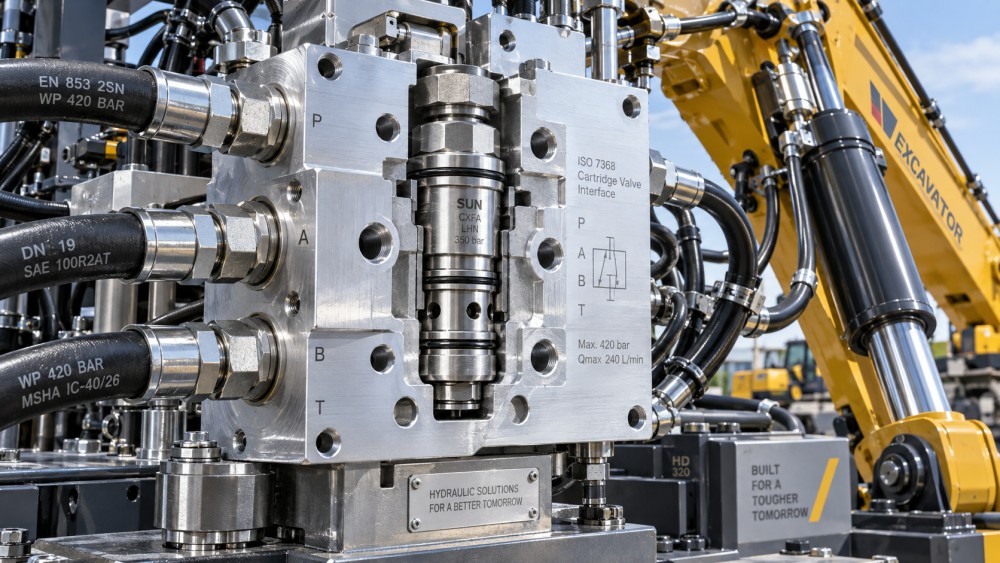
Hydraulic cartridge valves are widely used in excavators, loaders, agricultural equipment, lift platforms, forestry machinery, mobile cranes, compact utility vehicles, and other machines where manifold integration saves space and reduces external plumbing. Their compact form is an advantage, but it also means that a poor selection can be hidden deep inside a valve block until it becomes a costly troubleshooting issue.
The most dependable selection sequence starts with the circuit function, then works through actual flow, pressure conditions, cavity standard, control method, fluid cleanliness, and service access. This approach prevents a common mistake: treating flow, pressure, and cavity size as separate choices when they are closely connected.
Start with the circuit function, not the valve family
“Cartridge valve” describes a mounting format rather than one specific control function. Before comparing models, define what the valve must do during normal operation, load changes, emergency events, and machine shutdown. A counterbalance valve on a boom circuit, for example, must manage load holding and controlled lowering. A relief valve must protect the circuit from pressure peaks. A proportional flow-control cartridge may be selected to regulate speed, while a directional poppet or spool cartridge determines where fluid is sent.
For mobile equipment, the main functional categories usually include:
- Pressure-control cartridges: relief, reducing, sequence, unloading, and counterbalance functions.
- Flow-control cartridges: fixed restrictors, pressure-compensated flow controls, priority valves, and flow dividers.
- Directional-control cartridges: check valves, logic elements, solenoid-operated poppet valves, and spool valves.
- Load-holding and motion-control valves: pilot-operated checks, hose-burst protection valves, and overcenter valves.
Function determines the performance questions that matter. A relief valve may tolerate a small, controlled pressure rise as flow increases. A proportional directional valve may need repeatable current-to-flow behavior and acceptable hysteresis. A check valve used in a high-cycle fan-drive circuit may need fast response and low cracking pressure. These requirements cannot be resolved by nominal size alone.
Flow rating: use the real operating flow, not only pump displacement
Flow is often the first number considered, yet it is frequently interpreted too simply. A cartridge valve’s published nominal flow may be based on a specified pressure drop, a particular fluid viscosity, and a defined test configuration. In a real machine, oil temperature changes, return-line backpressure rises, and several functions may be active simultaneously. The usable flow capacity is therefore tied to allowable pressure loss rather than a single nameplate number.
For a given orifice geometry, pressure drop rises rapidly as flow increases. In practical terms, doubling flow does not merely double restriction losses. This is why a valve that works well in a prototype at moderate speed may become a source of heat and sluggishness when the machine operates at full engine RPM or during combined functions.
Technical evaluators should establish at least four flow values before selecting hydraulic cartridge valves:
- Continuous flow: the normal sustained flow through the valve during typical work.
- Peak flow: the highest expected short-duration flow, including regenerative or combined-function conditions.
- Minimum controllable flow: especially important for proportional controls, low-speed actuator movement, and precise positioning.
- Reverse flow: relevant to check valves, pilot-operated valves, and bidirectional flow-control arrangements.
Consider a telescopic boom circuit. Extension flow may be moderate, but lowering can generate a different return flow because of cylinder area ratios and load-induced motion. A valve sized only for the pump’s supply flow may restrict the return side or make the lowering motion difficult to control. The cylinder’s annulus-to-piston area ratio, regenerative paths, and any parallel actuator operation should be reviewed early.
Pressure drop deserves a defined budget. Not every circuit needs the same target. A low-loss bypass path in an energy-sensitive machine may justify a larger cavity and valve body. In contrast, a compact pilot circuit may accept more restriction because its flow is small. What matters is that the accumulated loss through hoses, fittings, valve sections, filters, and cartridge passages remains compatible with available pump pressure and thermal capacity.
Pressure selection means more than choosing the highest available rating
Mobile hydraulic systems experience pressure transients that are more severe than steady gauge readings suggest. Sudden valve closure, swinging loads, external impacts, cylinder end-of-stroke events, and rapid directional reversals can create momentary peaks. A cartridge valve must have an appropriate pressure rating for the port where it is installed, but the surrounding manifold, seals, cavity thread, retaining method, and connected fittings must also withstand the same conditions.
Separate the following values during evaluation:
- System working pressure: the normal pressure during machine operation.
- Relief setting: the pressure at which protective control begins to open.
- Full-flow relief pressure: the pressure reached when the relief passes the required flow.
- Maximum intermittent pressure: short-duration exposure permitted by the valve supplier.
- Backpressure: pressure at the tank or return port that may affect valve behavior.
The distinction between relief setting and full-flow pressure is especially important. A direct-acting relief cartridge may begin to crack at one pressure but require a noticeably higher pressure to pass the full pump flow. If this pressure override is ignored, the machine may exceed the desired actuator or hose limit before relief flow is fully established. Pilot-operated relief designs can offer lower override and better high-flow behavior, though they introduce their own sensitivity to pilot passages, contamination, and installation details.
Pressure rating should also be considered in relation to fatigue. A valve used in a frequently reversing implement circuit is exposed to thousands of pressure cycles. The selection review should include duty-cycle frequency, expected load shocks, oil temperature, and the likelihood of pressure intensification. Intensification can occur when trapped fluid is heated or when unequal actuator areas create pressure multiplication under certain load conditions.
Cavity size is a system interface decision
Cavity size determines far more than whether a valve physically fits into the manifold. It influences flow area, pressure drop, available valve functions, installation torque, machining complexity, service tooling, and replacement options. In mobile equipment manufacturing, a standardized cavity can simplify service and allow different valve functions to share one manifold platform. However, “standardized” should not be confused with universally interchangeable.
Common hydraulic cartridge valve cavity families are often identified by industry size conventions, thread dimensions, or manufacturer-specific codes. A cavity may look similar to another one while differing in sealing lands, thread engagement, pilot passages, or shoulder geometry. Installing an incorrect cartridge can damage seals, bypass flow internally, or create a condition where the valve appears seated but cannot operate as intended.
When selecting a cavity, verify these points against the valve and manifold documentation:
- Cavity type, thread form, diameter, and depth.
- Location and dimensions of O-ring sealing surfaces.
- Port arrangement and internal flow path.
- Recommended installation torque and access for the torque tool.
- Required surface finish, concentricity, and burr control after machining.
- Compatibility with available manual, solenoid, or proportional cartridge versions.
A larger cavity generally supports greater flow with lower velocity and reduced pressure loss, but it takes more manifold material and may increase machining cost. It can also make a compact valve block harder to package near a boom, axle, or transmission housing. Conversely, selecting the smallest possible cavity may save space initially while limiting future upgrades or forcing higher oil velocity through a critical control path.
For OEM design teams, the best cavity is often the smallest one that meets continuous-flow, peak-flow, pressure-drop, pressure-rating, and serviceability requirements with a realistic operating margin. For retrofit and maintenance teams, cavity availability and interchangeability may carry more weight, particularly where machines operate in remote locations and downtime is expensive.
Valve behavior under changing load can matter more than nominal capacity
Mobile machines do not operate under laboratory-steady conditions. Loads shift, engines change speed, oil temperature rises after a long work cycle, and operators demand smooth motion at both low and high speeds. This is where dynamic characteristics become decisive.
For flow-control cartridges, review compensation range, flow regulation accuracy, sensitivity to viscosity, and behavior when inlet pressure approaches the compensation threshold. A pressure-compensated valve may provide stable actuator speed, but only when sufficient differential pressure is available. If the pump cannot maintain that margin during combined functions, speed control will deteriorate.
For pressure-control valves, evaluate hysteresis, pressure override, stability, and response to transient flow. A valve that oscillates can create noise, pressure ripple, and uncomfortable machine motion. In load-holding circuits, the interaction among counterbalance setting, pilot ratio, cylinder geometry, and directional valve metering is particularly important. A high setting may hold the load securely but require excessive pilot pressure to lower it. A low setting may reduce stability on an overrunning load.
Solenoid-operated cartridges deserve a separate electrical review. Confirm coil voltage, connector style, ingress protection suitable for the machine environment, power consumption, duty rating, manual override needs, and response at low battery voltage. In harsh construction or agricultural equipment, connector retention, wire routing, vibration resistance, and exposure to water or debris are practical concerns—not minor installation details.
Contamination, fluid temperature, and leakage are part of valve sizing
A cartridge valve may be correctly sized for flow and pressure yet fail prematurely because the fluid condition was considered too late. Tight-clearance spool valves and proportional cartridges can be sensitive to contamination. Poppet valves may tolerate certain contaminants better in some applications, but they are not immune to particle damage, seat wear, or sticking caused by varnish.
Selection should align with the machine’s filtration strategy and expected oil cleanliness level. Consider where the valve sits in the circuit: downstream of a pump, in a return line, at an actuator port, or within a pilot-control branch. A critical motion-control valve may require cleaner oil than a simple bypass function. Cold-start viscosity also matters. Thick oil can slow response and elevate pressure drop, while very hot oil can increase internal leakage and reduce damping.
Leakage expectations should be stated clearly. Internal leakage is normal in many spool-type valves and may be acceptable in a pilot circuit, but it can cause cylinder drift in a load-holding application. External leakage depends on proper O-ring material, cavity finish, installation torque, and compatibility with the hydraulic fluid and operating temperature range. Seal selection should account for conventional mineral oils as well as any specified biodegradable or fire-resistant fluids.
A practical evaluation checklist before release
Before approving a cartridge valve or manifold design, technical teams benefit from a short but disciplined review. Confirm the circuit schematic and identify every possible flow direction. Calculate continuous and peak flow at the actual operating speed. Compare pressure-drop curves at expected oil viscosity, not only at ideal test conditions. Check the relief behavior or control characteristic at full flow. Then verify cavity geometry against the latest machining drawing and ensure that assembly tools can reach the cartridge in the installed machine.
It is also wise to ask how the valve will be diagnosed in the field. Can pressure test points be placed near the relevant ports? Is the coil replaceable without removing a major machine structure? Are the cartridge markings visible after installation? Can procurement obtain equivalent service parts only when the cavity and functional specifications truly match? These questions often reveal lifecycle risks that are invisible in early CAD layouts.
Choosing for the machine’s lifetime, not just the first build
The right hydraulic cartridge valve selection creates a balanced result: enough flow capacity without unnecessary size, sufficient pressure margin without uncontrolled override, and a cavity design that supports both accurate manifold machining and realistic service access. The decision is not about finding the largest valve or the highest pressure rating. It is about understanding how the valve behaves in the specific circuit when the machine is hot, loaded, vibrating, and expected to keep working.
For evaluators comparing hydraulic and pneumatic equipment, IMPE encourages a documentation-led approach. Review hydraulic schematics, manifold cavity data, pressure-flow curves, fluid requirements, material information, inspection practices, and service conditions as one connected set of evidence. That level of review helps OEMs, equipment builders, distributors, and project teams reduce avoidable integration risk before a cartridge valve becomes a hidden weak point in an otherwise capable mobile machine.
Related News
- How to Assess a Rigid Coupling Supplier for Bore Accuracy and Traceable QualityOct 08, 2026Tribology & Kinematics Expert
- Titanium Alloys Compared: Balancing Strength, Corrosion Resistance, and MachinabilityOct 08, 2026CNC Kinematics Architect
- Where Ductile Iron Dismantling Joints Reduce Alignment Risk in Water PipelinesOct 08, 2026Pipeline Metallurgy Scientist
- Selecting a Precision Bearing Sleeve: Fits, Runout, and Material ChoicesOct 08, 2026Tribology & Kinematics Expert
- Face Milling Cutters: How Insert Geometry Affects Finish on Steel and AluminumOct 08, 2026CNC Kinematics Architect
- Single-Acting Cylinders for Clamping: Stroke, Force, and Return Spring ConsiderationsOct 07, 2026Fluid Power Control Strategist