
How Hydraulic Manifold Blocks Improve Cycle Control in Construction Equipment
Cycle control in construction equipment is rarely determined by pump capacity alone. An excavator boom that lowers too abruptly, a loader attachment that hesitates at reversal, or an outrigger circuit that drifts under load can all originate in the way hydraulic functions are routed, regulated, and isolated. Hydraulic manifold blocks improve this control by bringing critical flow and pressure functions into a rigid, closely coupled valve architecture rather than distributing them through a larger number of hoses, adapters, and separately mounted valves.
For machine builders and equipment upgrade teams, the practical benefit is not simply a smaller hydraulic package. A well-designed manifold can make actuator motion more repeatable across changing loads, reduce pressure losses caused by unnecessary plumbing, shorten response paths between valves and actuators, and make cross-function interactions easier to engineer. These gains matter most where a machine repeatedly performs short, load-sensitive movements: digging, lifting, grading, clamping, stabilizing, steering, or positioning.
Why cycle control becomes unstable in conventional hydraulic layouts
A construction machine cycle is the combined result of pump flow, valve metering, load pressure, actuator area, fluid condition, and the resistance created by lines and fittings. In a distributed layout, those elements may be separated by long hose runs, tee fittings, elbow adapters, standalone pressure-control valves, and external valve banks. Every connection introduces a potential restriction, leakage point, compliance change, or source of variation.
That variation does not always appear as a complete loss of function. More often, it shows up as inconsistent feel and timing. A cylinder may extend smoothly with a light bucket but become difficult to meter under a loaded condition. A function may react quickly when cold and differently after fluid temperature rises. One attachment circuit may take priority over another because the supply and return paths do not maintain the intended pressure relationship during combined movements.
Hose expansion is another factor. Flexible hoses are necessary in many mobile applications, but they also add hydraulic compliance. When a valve opens, part of the initial fluid displacement can be absorbed by line expansion before the actuator develops the expected motion. On a long line feeding a small pilot-operated circuit, this can be noticeable as delay or softness at the control input. The effect is more significant when several functions are switched rapidly or when proportional control must remain stable near the start and end of a stroke.
A manifold does not remove all of these system-level variables. It does, however, allow the designer to place directional, pressure, check, flow-control, and logic elements around a common internal flow network. This makes the hydraulic path shorter, more defined, and easier to coordinate.
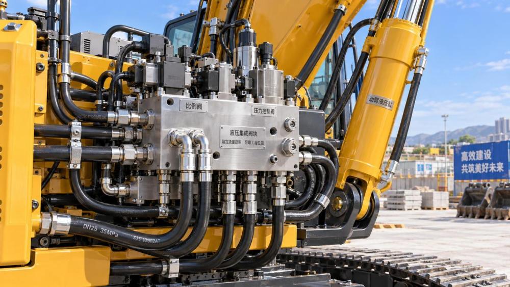
A manifold block is a control architecture, not just a drilled metal block
Hydraulic manifold blocks for construction equipment are commonly machined from aluminum, steel, or ductile iron, depending on pressure requirements, operating environment, weight targets, corrosion exposure, and required port configuration. Internal drilled passages connect cartridge valves, external ports, gauge locations, and mounting surfaces. The block may support a relatively simple attachment circuit or a multi-function control assembly containing proportional valves, relief valves, load-holding valves, shuttle valves, pressure-reducing valves, and pilot logic.
The important distinction is that a manifold defines how functions interact. Its internal passages establish which valve sees supply pressure first, where load-sense signals are collected, how return flow is managed, whether one actuator can influence another, and where protective pressure functions intervene.
For example, a boom-lift circuit may combine directional control with port relief protection, anti-cavitation checks, pilot-operated check valves, and a counterbalance valve. If these elements are selected and arranged correctly, the cylinder can hold a suspended load, lower it under controlled backpressure, and remain protected from transient pressure spikes. If the same elements are assembled externally with poorly matched line sizes or distant valve placement, the function may still operate, but its response and stability can be less predictable.
The manifold therefore should be reviewed as part of the machine’s motion strategy. It is not enough to confirm that the ports match the hose connections or that the cartridge cavities accept the intended valves.
How integrated flow paths improve motion repeatability
The first improvement comes from reduced flow-path complexity. Internal passages can be sized for the required flow rate and arranged to avoid unnecessary directional changes. This does not mean every passage should be made as large as possible. Oversized passages can increase block size and cost without improving the controlled function, while undersized passages create pressure drop, heat, and restricted actuator speed. Effective design starts with the flow required for each duty cycle, not with a generic port-size preference.
Pressure loss through plumbing affects available actuator force. When supply pressure is consumed by restrictive fittings, long hoses, or undersized passages, less pressure reaches the cylinder or motor. On return flow, restrictions can create unwanted backpressure that changes the speed of an overrunning load or interferes with valve spool behavior. A manifold allows supply, work, and tank galleries to be designed as a connected system, making these losses easier to identify before hardware is installed.
The second improvement is lower dead volume around control components. Fluid volume between a metering valve and an actuator acts as part of the dynamic system. Reducing unnecessary volume can sharpen response, particularly in pilot circuits and proportional functions. The outcome is not automatically “faster” motion; excessively abrupt response can make a machine difficult to control. The real objective is a stable and calibrated relationship between command input, valve movement, pressure development, and actuator motion.
The third improvement is better pressure-function coordination. A manifold can position a relief valve, sequence valve, or pressure-reducing valve close to the circuit it protects or regulates. This helps ensure that the valve responds to the pressure condition that matters, rather than to a delayed or distorted signal from a remote line. In a circuit with multiple work functions, that proximity can improve the consistency of priority and protection logic.
Cycle control is especially sensitive during load transitions
Construction equipment does not operate under one fixed load. A bucket curls through loose material, breaks out against compacted ground, swings with changing inertia, and may then dump under gravity-assisted motion. A telehandler or aerial platform changes load moment as its boom extends. A compactor, trenching attachment, or demolition tool can introduce rapid pressure fluctuations into the auxiliary circuit.
These transitions expose weaknesses in valve and manifold design. When a load changes from resistive to overrunning, the actuator can attempt to move faster than pump flow supplies it. Without sufficient backpressure and make-up flow, the circuit may cavitate, surge, or become difficult to meter. Counterbalance valves, anti-cavitation checks, and properly arranged work-port protection are often needed to manage this condition. Integrating them into a manifold can reduce the number of external connections and make their interaction with the directional valve more controlled.
For suspended loads, load-holding performance requires special attention. A pilot-operated check valve may prevent unintended cylinder movement, but its opening characteristics must be compatible with the directional valve and the available pilot pressure. A counterbalance valve can provide more controlled lowering, yet excessive setting pressure or poor pilot ratio selection can create pressure intensification, heat, or stick-slip motion. The manifold provides the physical platform for these devices; it does not compensate for incorrect circuit logic or valve settings.
Combined functions create another challenge. An excavator may lift, crowd, and swing at the same time. A loader may raise the arms while curling the bucket. If the manifold contains priority or flow-sharing functions, internal gallery design and valve selection determine whether one command starves another, whether the machine preserves a critical function, and how smoothly flow is reallocated when demand exceeds pump capacity.
Proportional control depends on more than the proportional valve
It is easy to assume that installing proportional cartridge valves will deliver precise machine motion. In reality, proportional performance depends on the entire hydraulic chain: command signal quality, solenoid force, spool characteristics, pressure differential, compensator behavior, pilot supply stability, fluid cleanliness, and the geometry of the manifold passages.
A proportional valve meters flow according to spool position, but actual flow also changes with pressure drop across the metering edge. If load pressure changes significantly, a non-compensated valve may produce different actuator speeds at the same electrical command. Pressure compensation can reduce that sensitivity by maintaining a more consistent pressure differential across the metering section. In multi-function equipment, flow-sharing arrangements may be required where maintaining predictable relative motion is more important than allowing one low-load function to consume the available flow.
Manifold integration can support these strategies by locating compensators, shuttle networks, and pilot passages close to the valve sections they serve. It can also reduce the chance that external plumbing introduces unintended restrictions into a sensitive signal line. However, internal signal passages must be designed with equal care. A small or poorly routed pilot gallery can create delay, damping, or pressure loss that is difficult to diagnose after the block is manufactured.
Electrical integration also deserves attention. Cartridge solenoids, connectors, harness routing, and ingress protection need to suit vibration, washdown, dust, and temperature exposure. A compact manifold may simplify hydraulic routing while creating a concentrated electrical service area. Clear labeling, protected connectors, and access for diagnostic measurement are practical requirements, not cosmetic details.
Where manifolds reduce installation risk—and where they can concentrate it
Replacing multiple externally connected valves with a manifold can reduce hose count, adapter count, and assembly time. Fewer joints generally mean fewer potential leak paths. The block can also provide a consistent mounting interface, which helps control installation quality across repeated machine builds. In tightly packaged equipment, this may free space for guarding, service access, or other machine systems.
Yet compactness can create a different form of risk. Once passages are machined into a block, late design changes are less forgiving than changing hose routing or replacing a standalone valve. An overlooked gauge port, incorrectly located return connection, inaccessible cartridge, or insufficient wrench clearance can turn a clean assembly into a service burden. Thermal concentration is another concern: if high-loss valves are placed in a compact body without considering duty cycle and heat rejection, local oil temperatures may rise.
Serviceability should be treated as part of cycle-control reliability. A machine cannot sustain predictable operation if a contaminated cartridge, damaged coil, or drifting pressure setting is difficult to inspect. Useful manifold provisions include accessible test points, clearly identified ports, cartridge retention that can be serviced in position, and isolation arrangements that avoid draining large parts of the circuit for a minor repair.
Material, machining, and cleanliness influence hydraulic behavior
The material choice for a manifold block should follow the operating envelope. Aluminum can reduce weight and is widely used in suitable pressure ranges, but thread strength, fatigue exposure, external damage risk, and corrosion conditions need assessment. Steel provides higher strength for demanding pressure and load conditions, although it adds weight and may require surface protection. Ductile iron can be appropriate for robust cast manifold bodies where geometry, production volume, and system requirements justify it.
Machining quality affects more than appearance. Port threads must maintain sealing integrity; cartridge cavities must meet the valve supplier’s dimensional requirements; intersecting drill paths must be properly deburred; and sealing faces must remain protected. Burrs or chips left in internal passages are particularly harmful because they can migrate into close-clearance spool valves, pilot orifices, and proportional cartridges.
Cleaning and preservation requirements should therefore be specified before production, not treated as a final packaging matter. The required cleanliness level depends on valve sensitivity and system architecture, but the core issue is consistent: a manifold must arrive free from machining debris, protected from corrosion, and sealed so that contamination is not introduced before installation. Flushing the completed machine remains necessary; it is not a substitute for clean manifold manufacture.
Design review questions that expose cycle-control problems early
The most useful review is based on operating states rather than a static hydraulic schematic. Each critical function should be examined during acceleration, steady movement, reversal, end-of-stroke approach, load pickup, load release, and simultaneous operation with other functions. Pressure and flow paths should be traced for each state.
- Does the actuator receive adequate flow at the required speed after line and valve losses are considered?
- When the load overruns the actuator, what creates the necessary backpressure and make-up flow?
- Which pressure relief device protects the work port, and can it respond to a transient at the location where it occurs?
- Does a priority function retain its intended behavior when pump capacity is insufficient for all commanded movements?
- Are pilot and load-sense passages protected from restrictions, cross-talk, and contamination?
- Can pressure be measured at supply, work, pilot, and return points without dismantling the installation?
- Are valve cavities, coil orientations, ports, and mounting features accessible after the manifold is installed on the machine?
These questions reveal why a manifold cannot be selected solely from a catalog flow rating. Nominal flow capacity is only one part of the decision. The relevant issue is whether the complete manifold circuit preserves the intended behavior under the machine’s actual duty cycle and load transitions.
Common assumptions that lead to disappointing results
One recurring mistake is treating a manifold as a passive connector plate. In a simple circuit it may function that way, but in construction equipment it often becomes the point where safety, controllability, and function priority are established. A block designed around convenience of machining rather than hydraulic logic can lock avoidable limitations into the machine.
Another mistake is specifying valves independently and assuming they will behave properly once installed together. Cartridge valves have interactions: a relief setting affects counterbalance operation; pilot pressure affects load-holding release; compensator selection affects proportional metering; return-line backpressure affects spool response. Compatibility must be evaluated at the circuit level.
It is also risky to pursue minimum package size without accounting for service access, heat, vibration isolation, and port loading. Hydraulic hoses should not impose excessive bending or side loads on the manifold ports. Mounting faces and fasteners must resist the vibration environment, while the block should be positioned away from likely impact zones and excessive radiant heat.
The strongest application of a manifold is not to eliminate every hose or compress every component into the smallest possible envelope. It is to create a hydraulic control assembly whose flow paths, protective functions, and maintenance points match the machine’s real operating sequence. When that alignment is achieved, cycle control becomes more consistent because the circuit has fewer uncontrolled variables between operator command, hydraulic pressure, and actuator movement.
Related News
- How to Assess a Rigid Coupling Supplier for Bore Accuracy and Traceable QualityOct 08, 2026Tribology & Kinematics Expert
- Titanium Alloys Compared: Balancing Strength, Corrosion Resistance, and MachinabilityOct 08, 2026CNC Kinematics Architect
- Where Ductile Iron Dismantling Joints Reduce Alignment Risk in Water PipelinesOct 08, 2026Pipeline Metallurgy Scientist
- Selecting a Precision Bearing Sleeve: Fits, Runout, and Material ChoicesOct 08, 2026Tribology & Kinematics Expert
- Face Milling Cutters: How Insert Geometry Affects Finish on Steel and AluminumOct 08, 2026CNC Kinematics Architect
- Single-Acting Cylinders for Clamping: Stroke, Force, and Return Spring ConsiderationsOct 07, 2026Fluid Power Control Strategist