
How Does a Globe Valve Perform in Water Main Throttling Control?
Globe valve throttling performance is critical to stable water main control, especially where utilities need accurate flow regulation, pressure management, and dependable operation.
A properly selected globe valve can provide highly predictable control across changing demand conditions, but its advantages must be weighed against pressure loss, energy use, and cavitation exposure.
For municipal utilities, EPC contractors, and industrial water operators, the key question is not whether globe valves can throttle, but when their performance justifies installation.
This article explains flow behavior, controllability, pressure drop, cavitation risk, materials, sizing, actuator selection, and practical operating limits for water transmission systems.
Why Globe Valves Are Effective for Water Main Throttling
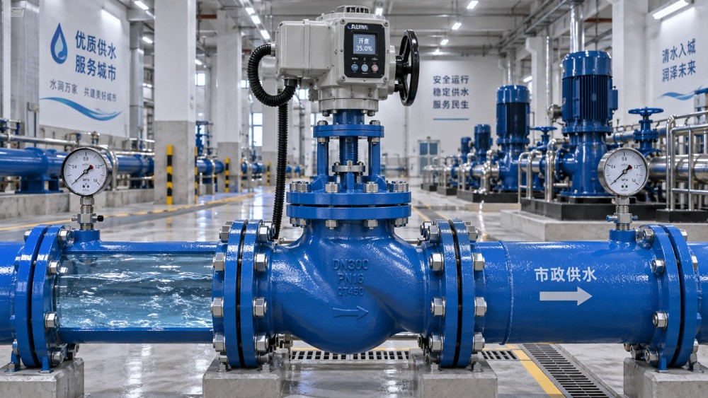
A globe valve is designed around a movable plug and seat arrangement, allowing operators to change the flow opening with relatively fine positional control.
Unlike many isolation valves, the globe valve’s internal geometry is intended to regulate fluid passage rather than simply provide a fully open or closed condition.
During water main throttling control, the plug moves toward or away from the seat, progressively changing the available flow area and system resistance.
This characteristic makes globe valves useful where a utility must maintain downstream pressure, limit filling rates, balance parallel mains, or control treatment plant flow.
The valve creates a defined restriction at the seat, so a relatively small stem movement can produce a measurable and repeatable change in flow.
That response gives operators more adjustment precision than many gate valves, which are primarily intended for isolation and can suffer damage when partially open.
Globe valve throttling performance is especially valuable in controlled branches, pump discharge lines, bypass systems, reservoir outlets, and industrial process water circuits.
Its performance is strongest when the valve is sized for the expected operating range rather than selected solely according to nominal pipe diameter.
A valve that is oversized may operate close to its seat during normal demand, reducing control resolution and increasing localized velocity through the restriction.
A correctly sized globe valve places normal operation in a useful travel range, where small actuator movements produce stable and manageable flow changes.
How the Internal Flow Path Influences Control Quality
Conventional globe valves direct water through a body passage, across the seat, and into another chamber before it exits through the downstream port.
This changing flow direction produces more turbulence than a straight-through gate or butterfly valve, but it also creates the resistance needed for reliable throttling.
The plug, disc, and seat geometry determine how flow capacity changes as the valve opens, commonly described by the valve flow characteristic.
A linear characteristic produces approximately equal changes in flow capacity for equal increments of stem travel under constant pressure differential conditions.
An equal-percentage characteristic produces increasingly larger capacity changes as travel increases, often helping control systems handle broad variations in process demand.
For water distribution work, actual installed behavior also depends on the pipe system, pump curve, elevation profile, downstream demand, and pressure control strategy.
This is why catalog flow coefficients alone cannot define real globe valve throttling performance in a municipal or industrial network.
Engineers should evaluate the valve’s authority, meaning how much of the total pressure drop occurs across the valve at the intended operating point.
Too little valve authority can make control sluggish because piping friction and other restrictions dominate changes in system resistance.
Excessive authority may offer strong control response but wastes pumping energy and can increase noise, vibration, and cavitation risk.
Pressure Loss Is the Main Tradeoff in Globe Valve Selection
Globe valves generally impose more permanent pressure loss than gate valves, plug valves, or full-bore ball valves because their internal path is less direct.
That pressure loss is not automatically a defect; controlled pressure reduction is often the very function required in water main throttling applications.
The practical concern is whether the required pressure drop can be absorbed without imposing excessive operating cost on pumps or reducing downstream service pressure.
Engineers commonly use the flow coefficient, Cv or Kv, together with flow rate, fluid properties, and differential pressure to estimate valve capacity.
For clean water, calculations are comparatively straightforward, but the final selection should also account for future peak demand and minimum-flow conditions.
A valve selected only for maximum flow may be too large to control low-demand periods, particularly in systems with large daily demand variation.
Conversely, undersizing may require the plug to remain nearly fully open during peak flow, leaving little capacity margin and raising velocity inside the valve.
Water utilities should assess annual energy implications when a throttling valve operates continuously on a pumped transmission main.
In some cases, variable-speed pumping, pressure reducing valves, or a different valve configuration may reduce lifecycle energy costs more effectively.
The best solution balances capital expenditure, control accuracy, maintenance requirements, energy consumption, and the consequences of poor pressure management.
Cavitation Can Limit Globe Valve Throttling Performance
Cavitation occurs when local pressure near the valve restriction falls below water vapor pressure, forming vapor bubbles that later collapse downstream.
Bubble collapse can produce noise, vibration, surface erosion, trim damage, fluctuating control, and eventually leakage or loss of valve performance.
Globe valves are more exposed to cavitation when they handle high pressure drops, high velocities, low downstream pressures, or sustained partial openings.
The risk is not determined by pressure differential alone because body geometry, trim design, temperature, recovery factor, and operating position also matter.
A standard globe valve may be acceptable for moderate differential pressure, while severe service can require anti-cavitation trim or staged pressure reduction.
Multi-stage trim divides the pressure drop across several restrictions, reducing the chance that pressure falls sharply below vapor pressure at one location.
Low-noise and cavitation-control trims can cost more initially, but they may protect critical equipment and avoid disruptive maintenance in inaccessible mains.
Specification teams should request manufacturer calculations for cavitation index, predicted noise, outlet velocity, and expected trim suitability at all operating cases.
These cases should include startup, pump shutoff transition, night-flow conditions, bypass operation, emergency flow, and anticipated future network configurations.
Ignoring abnormal operating conditions is a common error because severe cavitation often occurs during transient or low-flow periods rather than design flow.
Materials, Trim, and Construction Determine Long-Term Reliability
Water main valve construction must match the water quality, external environment, pressure class, temperature range, maintenance access, and applicable project standards.
Ductile iron bodies are common in municipal service because they provide strength, durability, and cost efficiency for many treated water applications.
Carbon steel or stainless steel bodies may be selected for industrial systems, aggressive environments, higher pressures, or applications requiring specific material compatibility.
Internal trim selection is equally important because the plug, seat, stem, and guide surfaces experience concentrated velocity, friction, and repeated movement.
Stainless steel, hardened alloys, bronze, and engineered coatings may be used according to water chemistry, abrasive solids, corrosion risk, and duty cycle.
Hard-faced seating surfaces can improve resistance to erosion and wear, particularly where throttling occurs frequently or where suspended particles are present.
For potable water systems, coatings, linings, elastomers, lubricants, and wetted materials should comply with relevant drinking water approval requirements.
External corrosion protection also deserves attention, especially for buried chambers, coastal sites, flooding-prone stations, and chemically aggressive soil conditions.
Epoxy coatings, corrosion-resistant fasteners, protective wraps, and suitable gland arrangements can extend service life when environmental conditions are challenging.
Buyers should require material certificates, pressure test records, coating documentation, dimensional data, and clear identification of all wetted trim components.
Valve Sizing Should Be Based on Operating Range, Not Pipe Size
A common procurement mistake is specifying a globe valve with the same nominal diameter as the main without evaluating required controllable flow capacity.
Line size is relevant for installation, but throttling performance depends more directly on flow rate, pressure differential, desired control range, and allowable velocity.
The selection process should begin with minimum, normal, maximum, and emergency flow conditions, together with upstream and downstream pressure limits.
Engineers can then calculate the necessary flow coefficient and compare available valve sizes, trims, and travel characteristics against those operating points.
Normal flow should generally occur in a stable middle section of travel, preserving control margin for demand changes in either direction.
Very low travel can make a valve sensitive to small actuator movements, while near-full travel can reduce effective control authority and available capacity.
Velocity limits should be reviewed through the seat and outlet because high local velocity can intensify erosion, noise, vibration, and cavitation potential.
For automated control, the actuator must generate sufficient thrust under maximum differential pressure while maintaining accurate and repeatable stem positioning.
Positioners, feedback devices, and compatible control signals help the system translate a pressure or flow command into actual valve travel.
Suppliers should provide sizing documentation rather than only a nominal pressure rating, because pressure class does not confirm satisfactory throttling behavior.
Actuation and Control Logic Affect Field Results
Manual globe valves are suitable for occasional balancing or fixed adjustments, but continuously changing water main conditions normally require automated actuation.
Electric actuators are common where electrical power and remote control infrastructure are available, offering straightforward integration with supervisory control systems.
Pneumatic or hydraulic actuators may be preferred where fast response, high thrust, existing utility systems, or hazardous-area requirements influence the design.
Actuator speed should match the hydraulic behavior of the network because overly rapid movement can create pressure transients and water hammer.
Control loops should use reliable pressure, flow, or level measurements positioned where they represent the actual process objective rather than local disturbances.
A downstream pressure-control loop, for example, may need filtering and tuning to avoid continuous hunting as demand changes across the network.
Fail position is another essential decision, since a valve may need to fail open, fail closed, or remain in position depending on system safety requirements.
Commissioning should confirm stroke direction, travel limits, calibration, control response, alarms, and interaction with pumps, pressure reducing stations, and bypass lines.
When a Globe Valve Is the Right Choice
A globe valve is a strong choice when precise and repeatable throttling is more important than achieving the lowest possible pressure loss through the valve.
Typical applications include treatment process control, pump recirculation, service reservoir outlets, industrial cooling water, controlled bypass lines, and pressure-managed branches.
It may be less attractive for large-diameter mains requiring low head loss, simple isolation duty, or very high flow where alternative control valve designs perform better.
Butterfly, plug, needle, diaphragm, pressure reducing, or specialized control valves can be more suitable depending on flow range, pressure drop, and water quality.
Selection should therefore be based on duty analysis rather than a generic preference for one valve type across an entire water network.
Project teams should compare initial price with expected energy use, trim life, maintenance access, spare part availability, control accuracy, and failure consequences.
Clear specifications and supplier data review reduce the risk of purchasing a mechanically acceptable valve that performs poorly under real throttling conditions.
For critical infrastructure, factory acceptance testing and documented performance verification provide additional confidence before field installation and commissioning.
Conclusion
Globe valve throttling performance can be excellent in water mains when accurate flow or pressure regulation is required across a defined operating range.
Its principal strengths are controllability, repeatable positioning, robust trim options, and suitability for automated process control in municipal and industrial systems.
Its main limitations are higher pressure loss and potential cavitation under severe differential pressure, especially when sizing or trim selection is inadequate.
Utilities and EPC teams should evaluate actual flow conditions, valve authority, pressure recovery, materials, actuation, and lifecycle energy before specifying a globe valve.
When these factors are addressed early, a globe valve can deliver stable water main throttling control, protect downstream assets, and support dependable long-term operation.
Related News
- How to Assess a Rigid Coupling Supplier for Bore Accuracy and Traceable QualityOct 08, 2026Tribology & Kinematics Expert
- Titanium Alloys Compared: Balancing Strength, Corrosion Resistance, and MachinabilityOct 08, 2026CNC Kinematics Architect
- Where Ductile Iron Dismantling Joints Reduce Alignment Risk in Water PipelinesOct 08, 2026Pipeline Metallurgy Scientist
- Selecting a Precision Bearing Sleeve: Fits, Runout, and Material ChoicesOct 08, 2026Tribology & Kinematics Expert
- Face Milling Cutters: How Insert Geometry Affects Finish on Steel and AluminumOct 08, 2026CNC Kinematics Architect
- Single-Acting Cylinders for Clamping: Stroke, Force, and Return Spring ConsiderationsOct 07, 2026Fluid Power Control Strategist