
High-Pressure Control Valves: Pressure Ratings, Cv, and Seal Choices Explained
A high-pressure control valve should not be selected by pressure rating alone. A valve can have a body rated above the system's maximum pressure and still perform poorly if its Cv is oversized, its trim is exposed to excessive differential pressure, or its seals are incompatible with the fluid and temperature. For technical evaluators, the useful question is whether the complete valve assembly can control the required flow through the full operating envelope without leakage, instability, excessive noise, cavitation, extrusion, or premature wear.
That assessment starts with three linked decisions: establish the pressure conditions the valve will actually see, size the flow path for controllable rather than merely maximum capacity, and select sealing materials for the combined effects of fluid chemistry, temperature, pressure cycling, and contamination. High pressure control valves used in hydraulic power units, process skids, energy equipment, test systems, and heavy machinery often fail at the interfaces between these decisions, not because one catalog parameter was obviously wrong.
Pressure rating is a boundary, not a performance guarantee
A published pressure rating usually describes the maximum pressure that a defined valve construction can withstand under stated conditions. It may apply to the body, end connections, bonnet, actuator interface, or the fully assembled valve. It does not automatically confirm that the valve will provide stable throttling at every pressure drop below that limit.
Technical reviews should separate at least four pressure values:
- Maximum upstream pressure: the highest pressure expected at the valve inlet, including credible pump excursions, surge events, and startup conditions.
- Normal operating pressure: the pressure range in which control quality and service life are expected.
- Differential pressure across the trim: the pressure reduction imposed between inlet and outlet at a given valve position and flow.
- Shutoff differential pressure: the pressure the valve must hold when closed or near closed.
These values are related but not interchangeable. A valve installed in a 350 bar hydraulic circuit may have a 350 bar body rating, while the actual trim sees only a modest differential pressure in normal service. Another valve in the same nominal pressure class may be required to throttle nearly the entire system pressure during a bypass or pressure-control event. The second duty is substantially more demanding, especially if it occurs frequently.
Shutoff requirements deserve separate attention. A valve may be suitable for high-pressure flow regulation but have a lower allowable pressure differential for tight shutoff, particularly when soft seats are used. Conversely, a metal-seated design may tolerate a severe shutoff differential but permit more leakage than an elastomeric or polymer-seated alternative. The specification should define whether leakage is acceptable, how it is measured, and under what pressure direction and temperature.
Pressure transients can be more important than steady-state line pressure. Rapid actuator movement, pump switching, downstream valve closure, trapped-fluid thermal expansion, and load reversal can create short-duration pressure peaks. A design review should identify their likely direction and frequency. A single occasional spike calls for a different response than repeated cycling near the pressure limit. Recurrent high-amplitude cycling affects fatigue life in the body and pressure-containing joints, while also accelerating seal wear and changing actuator loading.
Connection ratings must be checked as part of the assembly. A high-pressure valve body connected through an underspecified flange, tube fitting, threaded adapter, hose, or manifold block does not create a high-pressure system. Thread form, material, wall thickness, assembly torque, and the relevant piping standard all matter. This is particularly important where a compact cartridge valve is installed in a custom manifold: the cartridge may be capable of the required pressure, but the cavity geometry, manifold material, and machining quality can become the limiting factors.
Cv must be sized for controllability, not just flow capacity
Cv expresses a valve's flow capacity under defined reference conditions. It is useful, but a Cv value without the required flow, pressure drop, fluid properties, and intended control range is not enough for selection. A large Cv may reduce pressure loss when the valve is fully open, yet create poor resolution at normal flow. A small change in stem position can then cause a disproportionate change in flow, producing hunting or unstable loop behavior.
For incompressible liquids, a commonly used sizing relationship is:
Cv = Q × √(SG / ΔP)
where Q is liquid flow in US gallons per minute, SG is specific gravity relative to water, and ΔP is the pressure drop across the valve in psi. Equivalent metric sizing methods are available, but the physical lesson is unchanged: required capacity rises with flow, while a greater allowable pressure drop permits a smaller flow area.
The formula is a starting point, not a final answer. It assumes conditions that may not hold when a valve operates near cavitation, flashing, choking, or a regime where viscosity has a material effect. In hydraulic oils, low-temperature viscosity can materially alter flow behavior and pressure loss. In process service, changes in liquid density, entrained gas, suspended solids, or fluid temperature can make a nominal Cv calculation misleading.
Good sizing begins by defining at least three duty points: minimum controllable flow, normal flow, and maximum required flow. The evaluator should then consider the available pressure differential at each point. A valve sized only for maximum flow often spends most of its life nearly closed. That creates high local velocity, poor control resolution, and a greater tendency toward trim damage. A valve that is too small, by contrast, can remain near fully open during normal operation and lose the ability to correct disturbances.
Valve characteristic also matters. An equal-percentage characteristic provides progressively larger flow changes as travel increases and can suit systems where the valve pressure drop changes widely with load. A linear characteristic produces a more proportional relationship between travel and flow under more stable pressure conditions. Quick-opening behavior can be appropriate for on-off or protective functions, but it is usually a poor default for continuous regulation.
The installed characteristic may differ sharply from the inherent characteristic shown on a data sheet. Pipe losses, parallel branches, pump curves, downstream restrictions, and changes in fluid viscosity all alter the pressure available across the valve. For a control valve in a recirculation line, for example, the valve may see one differential pressure when the system is cold and another after fluid temperature rises or downstream equipment changes state. A selection based only on one nominal operating point can therefore look acceptable in calculation and perform poorly in service.
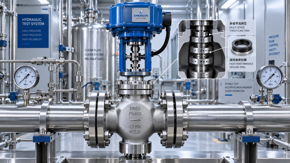
High differential pressure changes the trim selection
When a valve dissipates a large pressure drop, the risk is not limited to loss of energy. Local pressure inside the flow path can fall below vapor pressure, creating vapor cavities that subsequently collapse as pressure recovers. This cavitation can pit metal trim, increase vibration, generate noise, and shorten service life. Flashing is different: once pressure falls below vapor pressure and remains there downstream, vapor persists and can cause erosive high-velocity flow.
High-pressure liquid service should therefore be reviewed for the pressure profile through the valve, not simply inlet and outlet pressure. Multi-stage pressure reduction, anti-cavitation trim, drilled cages, labyrinth paths, or staged restrictions may be justified where a single throttling point would absorb too much differential pressure. These designs divide the pressure drop and reduce local velocities, though they can be more sensitive to contamination and may impose a higher permanent pressure loss.
In gaseous service, the corresponding concern is choking: a condition in which increasing the downstream pressure reduction no longer produces proportional additional mass flow. Noise, vibration, and high outlet velocity can become dominant selection factors. The actuator and positioner must also be evaluated against the forces generated by the maximum differential pressure, not merely against the force needed to move the stem under benign conditions.
Trim material should match the expected damage mechanism. Hardened stainless steels, cobalt-based hardfacing, tungsten carbide, ceramics, and engineered coatings may be used where erosion, particle abrasion, or repeated high-velocity throttling are expected. The appropriate choice depends on fluid cleanliness, corrosion exposure, thermal cycling, and repair strategy. Hard trim is not automatically superior: some hard materials are less tolerant of impact, difficult to rework, or unnecessary in clean, moderate-duty service.
Seal choice is a system compatibility decision
Seals in high-pressure control valves include stem packing, O-rings, seat seals, backup rings, diaphragm elements, piston seals, and actuator seals. Their performance depends on more than chemical compatibility with the process fluid. Pressure differential, temperature, cycling rate, extrusion gap, surface finish, installation damage, lubrication, and particulate contamination all influence service life.
Nitrile rubber is widely used in many mineral-oil hydraulic applications because it offers practical oil resistance and cost control within moderate temperature limits. Fluorocarbon elastomers are often considered where higher temperatures or broader chemical resistance are required. Ethylene propylene rubber can be suitable for water-based media and some steam-related conditions, but it is generally unsuitable for petroleum oils. Perfluoroelastomer materials can address demanding chemical and thermal environments, although their cost and mechanical limitations need to be assessed against the duty.
These broad material categories do not replace compound-level validation. Two seals described by the same polymer family can differ in hardness, filler system, curing chemistry, low-temperature behavior, and resistance to a particular additive package. Hydraulic fluids may contain anti-wear, fire-resistant, water-glycol, phosphate ester, or synthetic-base formulations that materially change compatibility. Process streams can also contain cleaning chemicals, inhibitors, solvents, or trace constituents that are more aggressive than the primary fluid.
At high pressure, extrusion is often the governing seal failure mode. A soft elastomer can be forced into the clearance gap between moving or static components, then cut or permanently deformed. Backup rings, tighter extrusion gaps, higher-durometer compounds, and improved gland geometry can extend seal life. However, reducing clearances or increasing seal stiffness may raise friction, increase breakaway force, and affect small-signal control response. That tradeoff is especially relevant in modulating valves with frequent small movements.
Temperature must be evaluated across the full cycle, including cold starts and possible upset conditions. At low temperature, some elastomers harden and lose resilience, raising leakage risk or actuator friction. At elevated temperature, compression set, chemical degradation, and loss of strength become more likely. A seal that appears acceptable at steady operating temperature can be unsuitable if the valve repeatedly moves through a much wider thermal range.
Actuation, leakage, and maintainability complete the evaluation
Valve body, trim, and seals cannot be assessed independently from the actuator. Pneumatic, hydraulic, electric, and electrohydraulic actuators all have different force, speed, fail-position, and control-resolution characteristics. The available actuator force must overcome process forces at maximum differential pressure, stem friction, packing load, spring force where applicable, and an appropriate operating margin. Undersized actuation often appears first as slow response, hysteresis, failure to seat, or inability to move under upset pressure conditions.
For critical duties, the specification should state the required fail action: fail closed, fail open, fail in place, or move to a defined safe position. This cannot be chosen from a generic preference. A recirculation valve protecting a pump, a valve isolating hazardous pressure, and a valve regulating a downstream process may require different failure behavior. Utility availability, loss-of-signal response, and manual override provisions should be consistent with that decision.
Documentation should support the claimed operating envelope. Useful items include pressure-temperature limits, Cv and flow-characteristic data, allowable shutoff differential pressure, leakage classification or test criteria, wetted-material identification, seal compound details, actuator sizing basis, connection specifications, pressure-test records, and material traceability where the service requires it. For severe pressure service, the evaluator should also ask how trim, packing, and soft parts are replaced, whether spare kits are traceable to the valve configuration, and whether field service can preserve the required assembly tolerances.
The most defensible selection is usually the one that has been checked at the actual duty points rather than at one maximum rating. Define the pressure envelope, calculate flow needs with realistic pressure drops, assess cavitation or choking exposure, then verify that seal and actuator choices remain suitable across fluid, temperature, and cycling conditions. That process produces a valve specification that is easier to procure, commission, and maintain than one built around a single headline pressure number.
Related News
- How to Assess a Rigid Coupling Supplier for Bore Accuracy and Traceable QualityOct 08, 2026Tribology & Kinematics Expert
- Titanium Alloys Compared: Balancing Strength, Corrosion Resistance, and MachinabilityOct 08, 2026CNC Kinematics Architect
- Where Ductile Iron Dismantling Joints Reduce Alignment Risk in Water PipelinesOct 08, 2026Pipeline Metallurgy Scientist
- Selecting a Precision Bearing Sleeve: Fits, Runout, and Material ChoicesOct 08, 2026Tribology & Kinematics Expert
- Face Milling Cutters: How Insert Geometry Affects Finish on Steel and AluminumOct 08, 2026CNC Kinematics Architect
- Single-Acting Cylinders for Clamping: Stroke, Force, and Return Spring ConsiderationsOct 07, 2026Fluid Power Control Strategist