
Custom Tie Rod Cylinders: How to Specify Stroke, Mounting, and Seal Requirements
A custom tie rod cylinder should be specified from the motion it must control, the forces it will see, and the environment it must survive. Bore diameter and working pressure establish available force, but they do not determine whether the cylinder will resist side loading, avoid rod buckling, seal reliably, or fit the machine geometry. Stroke, mounting, rod details, and seal materials must be defined as a connected set of decisions.
For an OEM machine, press, handling system, mobile attachment, or industrial fixture, the most useful starting point is not a catalog model. It is a clear description of the load path: what moves, how far it moves, how often it cycles, where the force acts, whether the load is guided externally, and what fluid or contaminants the cylinder will encounter. That information turns a standard-looking actuator into a workable custom specification.
Start with the real stroke, not the available installation space
Stroke is the distance the piston travels between its retracted and extended positions. It seems simple, yet it is one of the most common sources of specification errors. A cylinder should provide the required working movement with enough allowance for mechanical tolerances, end-position adjustment, and any variation in the attached linkage. Specifying the distance between two machine components as the cylinder stroke can leave no margin for assembly variation or thermal movement.
First identify the required motion at the point where work is done. If the cylinder drives a pivoting arm, scissor mechanism, or linkage, cylinder travel is not necessarily equal to movement at the tool, clamp, or load. Link geometry can change the required cylinder stroke and the force throughout the travel. The position where the mechanism has the poorest mechanical advantage often deserves the most attention, because it may be the point of highest cylinder force demand.
Longer stroke also changes the mechanical risk. As extension increases, the unsupported length of the piston rod grows. A compressive load can then cause rod buckling before the hydraulic system reaches its intended pressure. This is especially relevant for slender rods, high-force pushing operations, vertically oriented cylinders, and cylinders mounted in a way that permits movement at both ends.
Do not use a longer stroke simply to create operational flexibility unless the machine genuinely needs it. Extra stroke can increase retracted length, hydraulic fluid volume, cycle time, and the buckling exposure of the rod. Where adjustment is needed, it may be better to use a mechanical stop, an adjustable clevis arrangement, external position sensing, or a revised linkage rather than treating unused cylinder travel as a design reserve.
Check the retracted and extended envelope
A stroke requirement must be checked against both installed lengths. The retracted dimension affects whether the cylinder can fit within the machine frame. The extended dimension affects clearance, hose routing, guarding, and the travel path of connected components. A cylinder that fits in a CAD side view may still interfere with a bracket, service cover, tire, conveyor frame, or operator guard as it swings through its mounted arc.
End cushioning should be considered separately from stroke. Hydraulic cushions can reduce impact as the piston approaches an end cap, but they are not a substitute for correct mechanical design. A rapidly moving, high-inertia load may still require controlled deceleration through the hydraulic circuit, external dampers, or a motion profile that reduces velocity before the end of travel. Hard mechanical stops should not routinely absorb the full energy of a moving load through the cylinder.
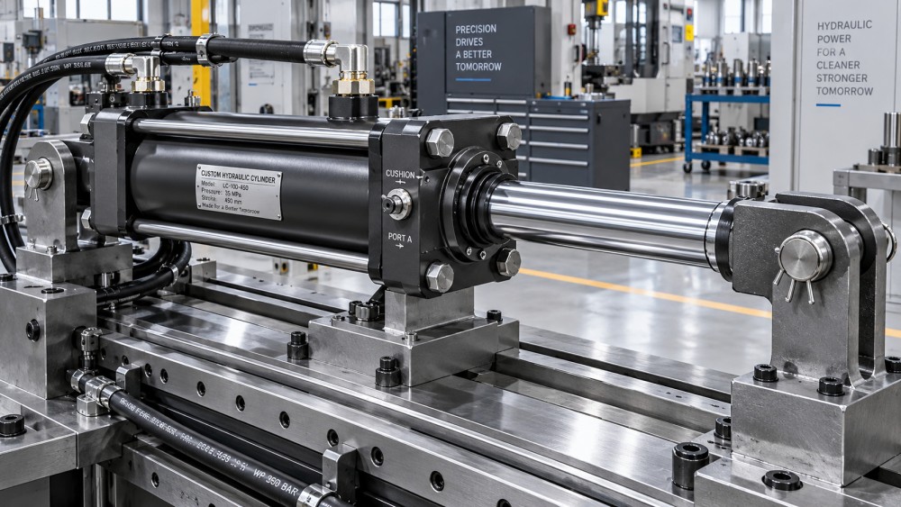
Mounting style determines how the cylinder carries load
Mounting is not merely a packaging choice. It determines the path through which the cylinder transfers force to the machine and how sensitive the assembly will be to misalignment. The best mounting style follows the motion of the load rather than the visual convenience of a mounting face.
Pin-mounted cylinders are often appropriate when the connected member rotates as it extends or retracts. The pins allow the cylinder to follow the arc instead of forcing the rod to bend. However, pin mounting does not automatically eliminate side loading. Misplaced pivots, worn bushings, poor bracket spacing, or a linkage that reaches an unfavorable angle can still introduce lateral force.
Flange-mounted and foot-mounted cylinders are better suited to controlled linear motion where the load has its own guides. A cylinder rod should transmit axial force; it should not be expected to guide a sliding platen, carriage, or heavy tool. Linear rails, wear strips, guide shafts, or a properly designed machine slide should absorb side load and moment load. When external guidance is weak, enlarging the cylinder bore may increase force but will not solve the alignment problem.
The direction of thrust matters for flange selection. A mounting arrangement that puts the highest load directly into a rigid end cap and machine structure can be more stable than one that relies on a less favorable load path. The design review should examine both extension and retraction. A cylinder may push a load in one direction and pull it in the other, with different force levels, guide behavior, and mounting stresses.
Specify rod diameter and end connection with buckling and fatigue in mind
The piston rod is sized by more than the cylinder bore. It must withstand tension, compression, side-load exposure, and the repeated stress of the duty cycle. A large-bore cylinder with a long stroke can generate substantial compressive force, making rod buckling the limiting condition. Conversely, a pull application may be governed by tensile loading at the rod thread, clevis, eye, or attached joint.
Rod buckling must be assessed using the actual end restraint. A rod supported by a rigid, guided load behaves differently from one connected to pivots that permit angular movement. The unsupported length also depends on the installation geometry at maximum extension, not only the nominal stroke. This is why a supplier needs the mounting arrangement and load connection, not just the bore, rod diameter, and stroke.
Rod-end style should match the machine interface. Threaded rod ends allow adjustment and flexible attachment, but the thread engagement, locking method, and stress concentration need attention. Clevises and spherical rod ends can accommodate angular movement; they are useful in linkage applications but should be selected with joint load, pin diameter, and wear in mind. A rigidly connected rod end belongs in an assembly with accurate alignment and independent load guidance.
Surface condition on the rod is equally practical. A rod finish suitable for a clean indoor machine may not tolerate abrasive slurry, welded spatter, salt exposure, washdown chemicals, or outdoor debris for long. Corrosion, scratches, and embedded contamination can damage dynamic seals and shorten service intervals. Rod boots, wipers, protective coatings, and physical guards are often more valuable than a modest change in cylinder force rating when the cylinder operates in a harsh area.
Seal selection must follow fluid, temperature, pressure behavior, and contamination
Seal requirements should be written as operating conditions, not as a generic request for “heavy-duty seals.” A cylinder seal package normally includes piston seals to separate pressure chambers, rod seals to retain fluid at the gland, wipers to exclude external contamination, and static seals at fixed interfaces. Each component handles a different failure risk.
The hydraulic fluid is the first filter. Seal compounds must be compatible with the fluid type and any additives in use. Temperature is the next filter, because it changes seal flexibility, extrusion resistance, friction, and aging behavior. A cylinder operating intermittently in a sheltered production area has a different seal demand from one exposed to outdoor temperature swings, hot equipment surfaces, or continuous cycling.
Pressure alone does not describe seal severity. Pressure spikes, rapid reversals, poor surface finish, contamination, and improper gland clearance can damage seals even when nominal system pressure appears reasonable. High pressure differential across a seal can also require measures that limit extrusion into clearance gaps. This is a cylinder design issue, not just a replacement-seal issue.
External contamination deserves specific wording in the request. Fine dust, metal chips, fibers, mud, water, fertilizer residue, or abrasive particles affect the wiper and rod-seal decision. A robust wiper can help prevent contaminants from being dragged into the gland during retraction, but it cannot compensate for a damaged rod surface or an exposed cylinder located directly in the debris stream. For washdown or corrosive environments, the specification should also cover exposed metal finishes, port protection, and any need for rod boots or bellows.
Low friction versus sealing margin
Some applications require smooth low-speed movement, accurate positioning, or low breakaway force. Others prioritize holding force, contamination resistance, and long service life under heavy loads. These goals can conflict. A lower-friction seal arrangement may improve motion control but may be less forgiving of contamination, pressure transients, or poor rod condition. A more robust sealing package may add friction and affect fine motion at low speed.
The right choice depends on the machine function. A cylinder used to clamp a part, lift a gate, or move a rugged attachment can accept different friction characteristics from one used in a controlled feed or synchronized positioning axis. The hydraulic circuit, valve behavior, and load guidance must be reviewed with the cylinder seals rather than treated as unrelated selections.
Define ports, cushions, sensing, and service access before releasing the drawing
Several details that appear secondary can decide whether the installed actuator is easy to operate and maintain. Port size and location influence pressure loss, hose bend radius, fitting clearance, and air bleeding. A port positioned for a neat drawing may be inaccessible after the cylinder is installed. The design should show hoses, fittings, guards, and nearby structure in both cylinder positions.
Position sensing can be useful where the control system needs confirmation of retracted, extended, or intermediate positions. It should be specified around the required feedback function and cable routing, not added as an afterthought. Similarly, adjustable cushions are worthwhile when motion energy and speed vary enough that end-of-stroke deceleration needs tuning. They add little value where the circuit already provides controlled deceleration and the load has low inertia.
Serviceability also belongs in the initial specification. Confirm whether the gland, seals, pins, fittings, and mounting hardware can be accessed without dismantling major machine sections. Tie rod cylinders are often selected because their construction can support practical maintenance, but that advantage disappears if the machine layout blocks disassembly or forces hose removal before basic inspection.
A practical specification package for custom tie rod cylinders
A purchase request becomes more reliable when it gives the cylinder manufacturer the operating context behind the dimensions. The following information usually prevents the most expensive revisions:
- Required push and pull loads, including any peak or holding condition.
- Stroke, retracted and extended installation dimensions, and allowable tolerance.
- Mounting type, pin or bolt details, bracket geometry, and the expected direction of movement.
- Bore and rod preferences when already established, plus the system pressure and available flow.
- Load guidance arrangement and any potential side or moment loads.
- Cycle pattern, speed requirement, dwell time, and expected end-of-stroke behavior.
- Hydraulic fluid, operating temperature range, external contaminants, corrosion exposure, and washdown conditions.
- Port locations, fitting restrictions, cushioning needs, sensors, protective features, paint or coating expectations, and service access constraints.
- Drawing requirements, inspection expectations, material traceability needs, and any site-specific documentation required by the project.
A simple force calculation is still essential. Extension force is based on pressure acting on the full piston area, while retraction force is lower because the rod occupies part of that area. But that calculation is only the starting point. Friction, dynamic loading, pressure losses, linkage angles, acceleration, and the load's own weight can all change the force actually required at the cylinder.
Do not use a custom cylinder to correct a weak mechanism
Custom tie rod cylinders are well suited to applications that need a defined stroke, non-standard mounting geometry, a particular rod end, special ports, tailored seals, or environmental protection beyond a catalog configuration. They are not a cure for an unrestrained carriage, a poorly aligned linkage, inadequate mounting brackets, or a hydraulic circuit that produces uncontrolled pressure spikes.
When a proposed cylinder repeatedly develops rod scoring, bent rods, leaking glands, loose pins, or damaged seals, the cylinder may be showing a machine-level problem. Investigate alignment, side load, guide wear, contamination entry, and end-of-stroke impact before increasing bore size or selecting a harder seal compound. Those changes can mask the original condition while creating a more costly failure mode.
For industrial purchasing and design reviews, platforms such as Global Industrial Machining & Piping Equipment Network (IMPE) can help organize the related questions around fluid-power components, machining capability, materials, inspection, and supplier documentation. The useful outcome is a specification that lets suppliers assess the same operating conditions, rather than returning quotations for visually similar cylinders with different practical limits.
Release the cylinder specification only after the stroke envelope, load path, mounting behavior, rod stability, fluid compatibility, and environmental exposure have been reviewed together. That sequence produces a more dependable actuator selection than choosing a bore from force alone and trying to solve the remaining problems after installation.
Related News
- Using Industrial Air Blow Guns to Clear Chips Without Spreading DebrisOct 15, 2026Fluid Power Control Strategist
- Ductile Iron Pipe Valves: Which AWWA Standards Apply to Water Main Projects?Oct 15, 2026Dr. Elias Vance
- Why Vacuum Suction Cups Lose Grip on MDF in Woodworking MachinesOct 15, 2026CNC Kinematics Architect
- Choosing a Variable Displacement Piston Pump Manufacturer: What to VerifyOct 15, 2026Fluid Power Control Strategist
- Parallel vs. Angular Pneumatic Grippers for Confined Assembly StationsOct 15, 2026Fluid Power Control Strategist
- Die Castings vs. Investment Castings: Which Costs Less at Your Production Volume?Oct 14, 2026Foundry Phase-Change Fellow